

Determination of Partial Fill in Electrochemical Strips
a technology of electrochemical strips and partial filling, which is applied in the direction of liquid/fluent solid measurement, biomass after-treatment, enzymology, etc., can solve problems such as erroneous readings
- Summary
- Abstract
- Description
- Claims
- Application Information
AI Technical Summary
Problems solved by technology
Method used
Image

Examples
example 1
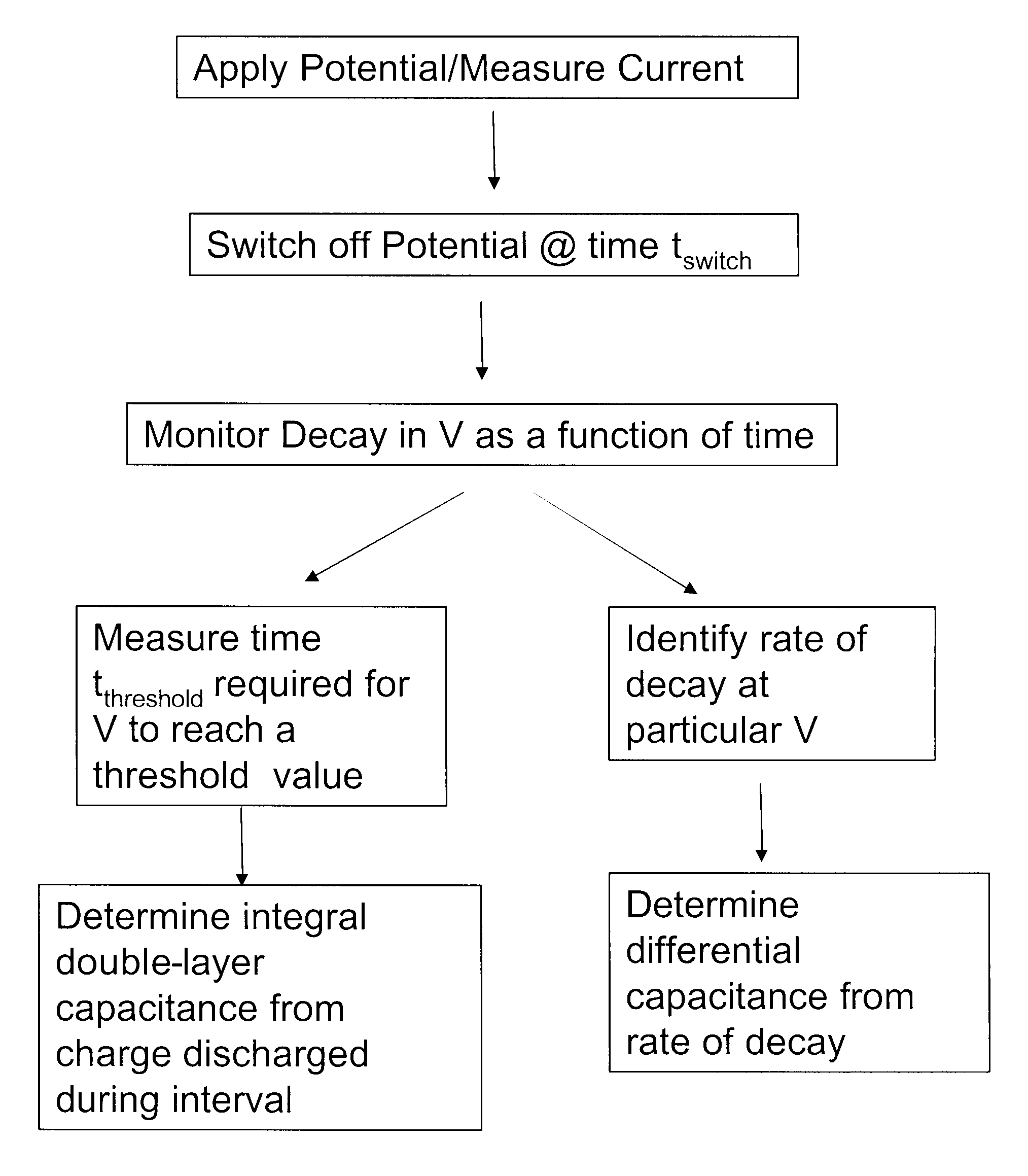
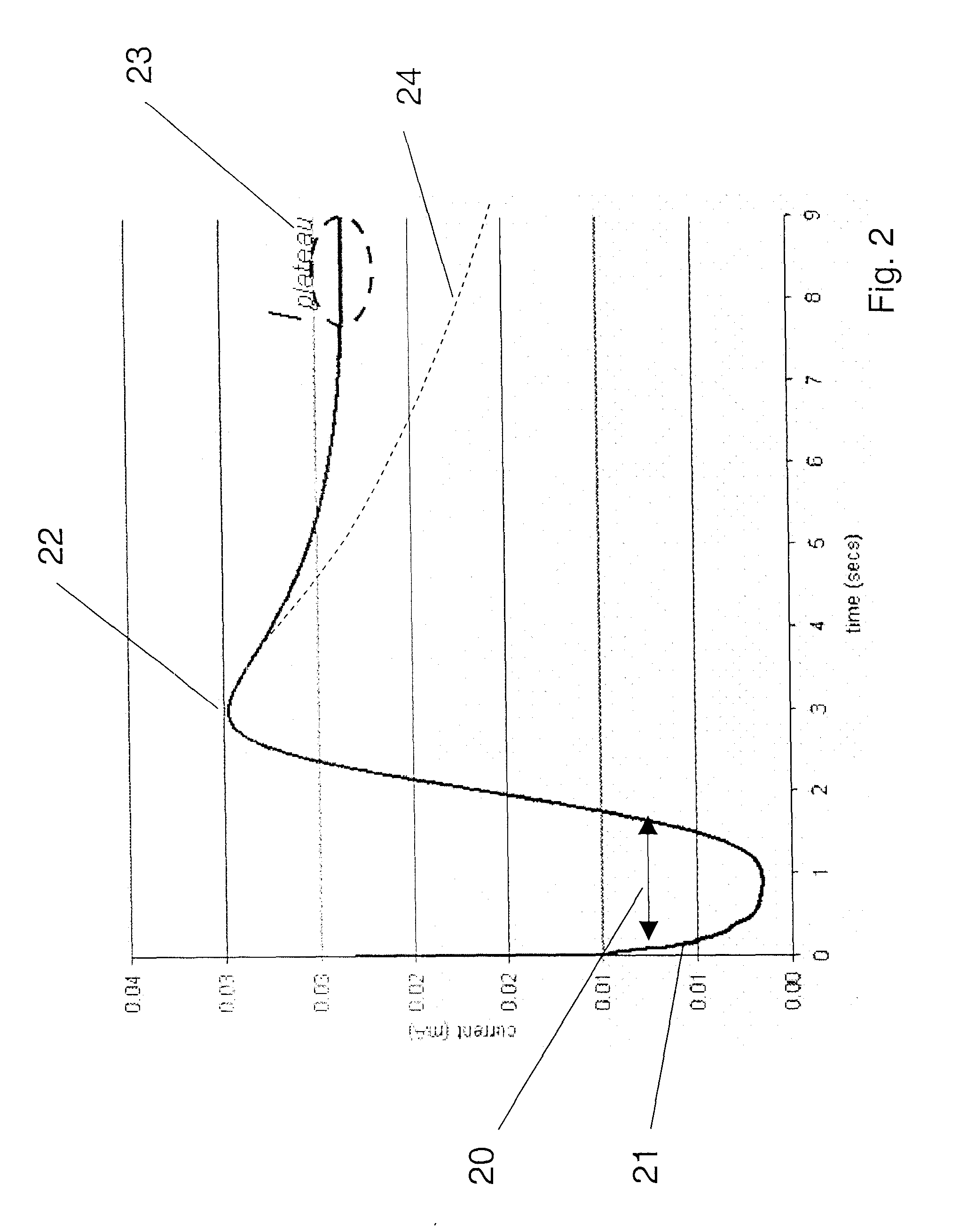
[0122] 300 mV was applied to electrochemical test strips, and maintained until a plateau current was observed. The applied voltage was then switched off, and the potential difference between the working and counter electrodes was measured. Differential capacitance was determined for a plurality of samples having varying glucose concentrations (3.17 to 16.5 mM) and hematocrits (20, 40 or 60), at different potentials relative to the counter electrode. The results are summarized in FIG. 10. It should be noted that because the x-axis shows potential difference, the right hand side of the graph reflects measurements done at lower voltage drops.
[0123] As shown in FIG. 10, while the curves are not regularly dependent on concentration or hematocrit, the differential capacitance for a given sample / test strip varies significantly with the potential at which it is measured. Further, the graph shows a region 100 in which the change in Cdif with voltage is less, and it is in this region of volt...
example 2
[0124] 300 mV was applied to electrochemical test strips with blood samples having either 2.79 mM or 20.2 mM glucose until a plateau current was observed. The applied voltage was then switched off, and the charge passed in discharging the double layer from 250 mV to 150 mV was measured. 300 mV was then reapplied, and the charge passed to recharge the double layer to 250 mV was observed. The relationship between the charging and discharging current was observed to be substantially linear with a zero intercept. However, the charge determined for recharging was lower than that for discharging, indicating that the measurement time of 100 ms was not sufficient for the recharging double layer to fully equilibrate with the solution. The observed amounts of charge were independent of glucose concentration, although the higher concentration decayed markedly faster.
example 3
[0125] 300 mV was applied to electrochemical test strips with blood samples having varying hematocrit levels (20, 40, or 60) and glucose concentrations of 3.87 mM, 10.2 mM or 20.1 mM until a plateau current was observed. The applied voltage was then switched off and differential capacitance was determined at 40 mV below Velectrode. Strips were designated as filled or partial fill based on the observation of sample in the viewing window. FIG. 11 shows the measured differential capacitance for a variety of strips. In FIG. 11, the glucose concentration is indicated by line type (solid=3.87 mM, dashed=10.2 mM and dot-dash=20.1 mM); and the hematocrit by symbol shape (diamond=20; triangle=40; square=60). Filled symbols indicate filled test strips, while open symbols indicate partial fills. The horizontal line in FIG. 11 is a threshold level of differential capacitance set at 1.7 μF that could be used with this test strip in assessing sample sufficiency. As shown, all of the filled sample...
PUM
| Property | Measurement | Unit |
|---|---|---|
| voltage | aaaaa | aaaaa |
| time | aaaaa | aaaaa |
| voltage | aaaaa | aaaaa |
Abstract
Description
Claims
Application Information