Method for Determination of Analyte Concentrations and Related Apparatus

a technology of electrochemical test strips and analyte concentration, which is applied in the direction of liquid/fluent solid measurement, enzymology, biomass after-treatment, etc., can solve the problems of inability to deal with samples and test devices, lengthen the time required to do a measurement, etc., and achieves improved reliability, reduced time required, and superior performance.

Active Publication Date: 2006-10-19
AGAMATRIX INC
View PDF19 Cites 123 Cited by
  • Summary
  • Abstract
  • Description
  • Claims
  • Application Information

AI Technical Summary

Benefits of technology

[0006] When determining analyte from a measurement of Cottrell current, the starting time, tmeas for the measurement is established dynamically at a time after tpeak when the observed current profile substantially conforms to Cottrell decay. In specific embodiments, this time set is a multiple of the time of maximum observed current, tpeak, where the multiple is determined for a given test strip configuration. In other embodiments, the tmeas is tpeak+a

Problems solved by technology

This compromise lengthens the time required to do a measurement, and may still fail

Method used


Image

  • Method for Determination of Analyte Concentrations and Related Apparatus
  • Method for Determination of Analyte Concentrations and Related Apparatus
  • Method for Determination of Analyte Concentrations and Related Apparatus

Examples


example 1

[0079] A meter with dynamic determination of tmeas using tpeak was used to evaluate finger-stick blood samples from a number diabetic patients, with no selection based on ages, genders, or ethnicity. The samples thus encompassed a good spread of blood physiologies, including different hct levels and different glucose levels. The test strip employed had facing screen printed carbon electrodes, and a nominal sample volume of 625 nanoliters. Since tpeak depends on both mobility of mediator (affected by hct) and by the concentration of glucose (if there is higher glucose, then more of the mediator must diffuse to the counter electrode, thereby taking more time), this sampling produced signals with a good range of different tpeak values.

[0080] The meter did the measurement, which was to do amperometry until enough Cottrell data was gathered (tmeas region), and made glucose determinations based on the Cottrell data. The meter also stored the total time from sample introduction to LCD dis...

example 2

[0081] In order to determine the appropriate coefficient to apply in modifying tpeak to determine tmeas, measurments are taken on matrix of samples with a range of hct and glucose concentrations in amperometric mode. An exemplary matrix is

[0082] hct=0, 20, 40, 60, 65%

[0083] [glu]=˜2 mM up to ˜30 mM

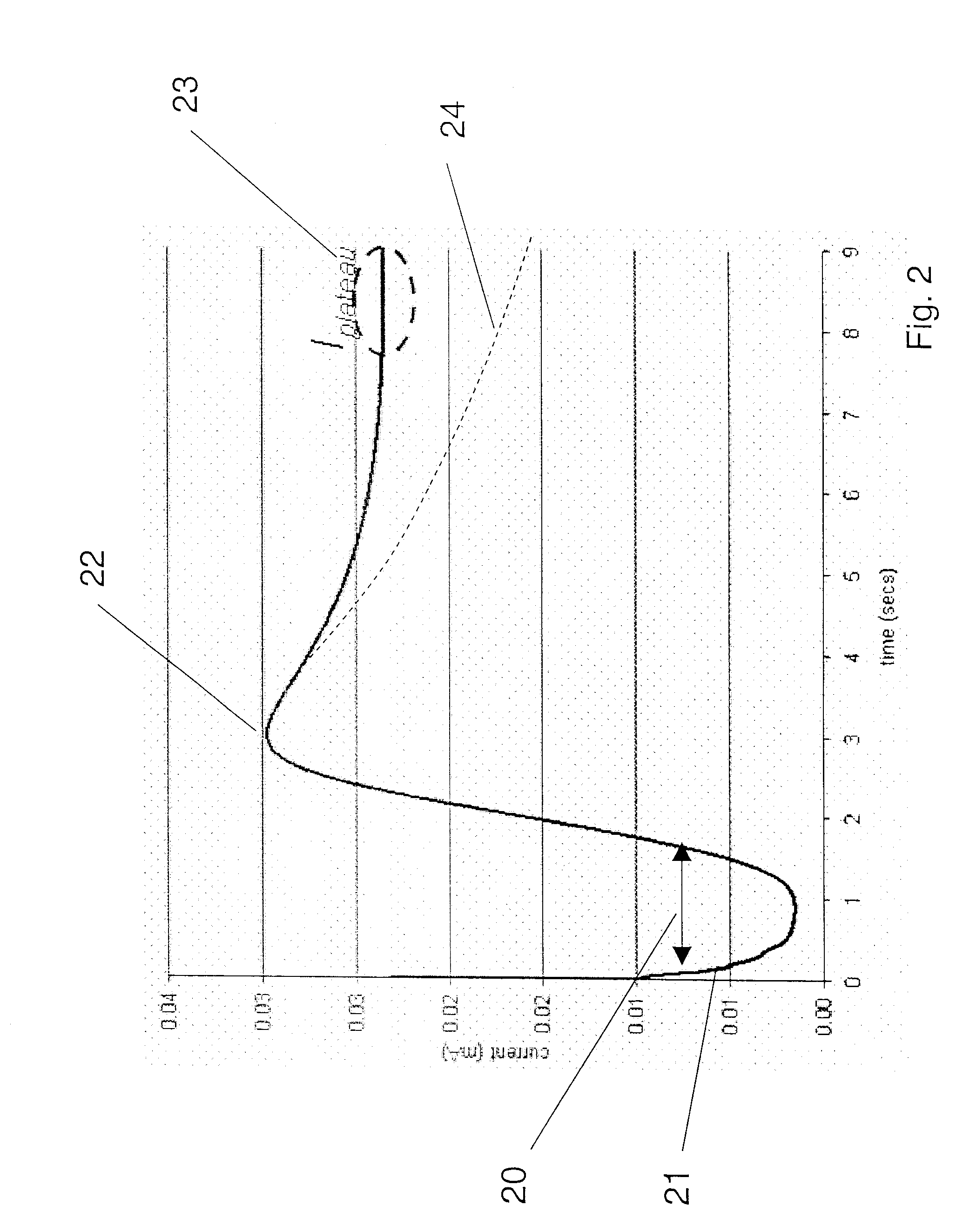
[0084] although the important thing is to select ranges that are representative of typical users. For each each glu / hct combination, replicate measurements are made, and the amperometric data (current vs. time) is compiled.

[0085] The data is processed in any of several different ways (as described in FIGS. 3A-D to arrive a value of tmeas. for each data point. The relationship between tpeak and tmeas for all the data spanning the range of glucose concentration and hct levels is plotted. The plotted data points are then fit to a linear model, indicating whether the correction is best modeled as an additive correction, a multiplier, or both. Other models with additional terms may also be ...


PUM

PropertyMeasurementUnit
Frequencyaaaaaaaaaa
Frequencyaaaaaaaaaa
Fractionaaaaaaaaaa

Abstract

A method is provided for determining analyte concentrations, for example glucose concentrations, that utilizes a dynamic determination of the appropriate time for making a glucose measurement, for example when a current versus time curve substantially conforms to a Cottrell decay, or when the current is established in a plateau region. Dynamic determination of the time to take the measurement allows each strip to operate in the shortest appropriate time frame, thereby avoiding using an average measurement time that may be longer than necessary for some strips and too short for others.

Description

BACKGROUND [0001] This application relates to a method for detection of analyte concentration using an electrochemical test strip, and to a meter and meter test strip combination for use in such a method. [0002] Small disposable electrochemical test strips are frequently used in the monitoring of blood glucose by diabetics. Such test strips can also be employed in the detection of other physiological chemicals of interest and substances of abuse. In general, the test strip comprises at least two electrodes and appropriate reagents for the test to be performed, and is manufactured as a single use, disposable element. The test strip is combined with a sample such as blood, saliva or urine before or after insertion in a reusable meter, which contains the mechanisms for detecting and processing an electrochemical signal from the test strip into an indication of the presence / absence or quantity of the analyte determined by the test strip. [0003] Electrochemical detection of glucose is co...

Claims


Application Information

Patent Timeline
IPC IPC(8): C12Q1/00
CPCC12Q1/006G01N27/307G01N27/3273C12Q1/00G01N27/49G01N27/3272G01N27/4161G01N27/4166G01N33/48707
Inventor DIAMOND, STEVENHARDING, IANIYENGAR, SRIDHAR G.WEI, BAOGUO
Owner AGAMATRIX INC
Why Eureka
Try Eureka