Circuit and method for driving organic light-emitting diode

a light-emitting diode and circuit technology, applied in the field of driving circuits, can solve the problems of difficult application of the passive matrix driving method to a large screen and a high-precision display, the threshold voltage of the thin film transistor often has a voltage deviation of more than 1 volt, and the image necessary for the display device cannot be high quality, etc., to achieve the effect of high quality

Active Publication Date: 2006-10-19
SILICON DISPLAY TECH CO LTD
View PDF6 Cites 45 Cited by
  • Summary
  • Abstract
  • Description
  • Claims
  • Application Information

AI Technical Summary

Benefits of technology

[0027] Example embodiments of the present invention provide a driving circuit of an OLED which can apply a driving current to the OLED without being affected by a variation of a threshold voltage of a transistor used in an active matrix, and a method which can display an image having high quality using the driving circuit.

Problems solved by technology

However, the passive matrix driving method is difficult to be applied to a large screen and a high-precision display.
However, even though the thin film transistor is formed on the same substrate, there is a problem that a threshold voltage of the thin film transistor frequently has a voltage deviation of several hundreds of mV or more than 1 Volt.
For example, even though a same signal potential is supplied to the gate of the thin film transistor in different pixels, when the threshold voltage of the transistor included in each pixel is different, the current value flowing to the OLED deviates greatly from a value necessary for each pixel, and thus the high quality of the image necessary for the display device can not be obtained.
The threshold voltage can not avoid some degree of variation according to a manufacturing company or products.
However, it is difficult to be realistic in a manufacturing process of the display device.
Additionally, the driving current is greatly varied at an initial value of the threshold voltage due to the characteristic deterioration caused by a environment temperature and an usage for a long time.
In this case, the definition or brightness of the display is greatly varied, thereby decreasing rapidly life of the display device.

Method used


Image

  • Circuit and method for driving organic light-emitting diode
  • Circuit and method for driving organic light-emitting diode
  • Circuit and method for driving organic light-emitting diode

Examples


example 1

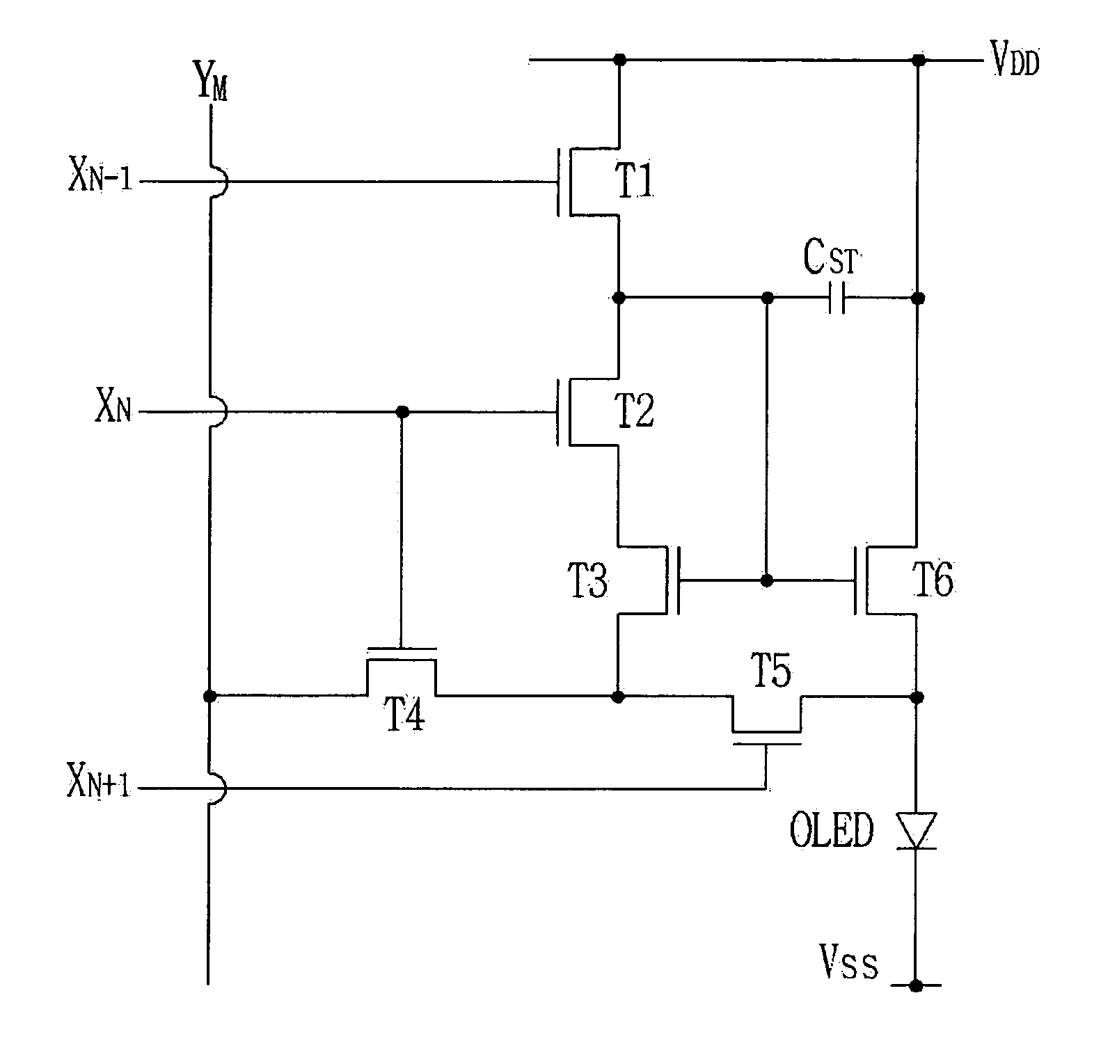
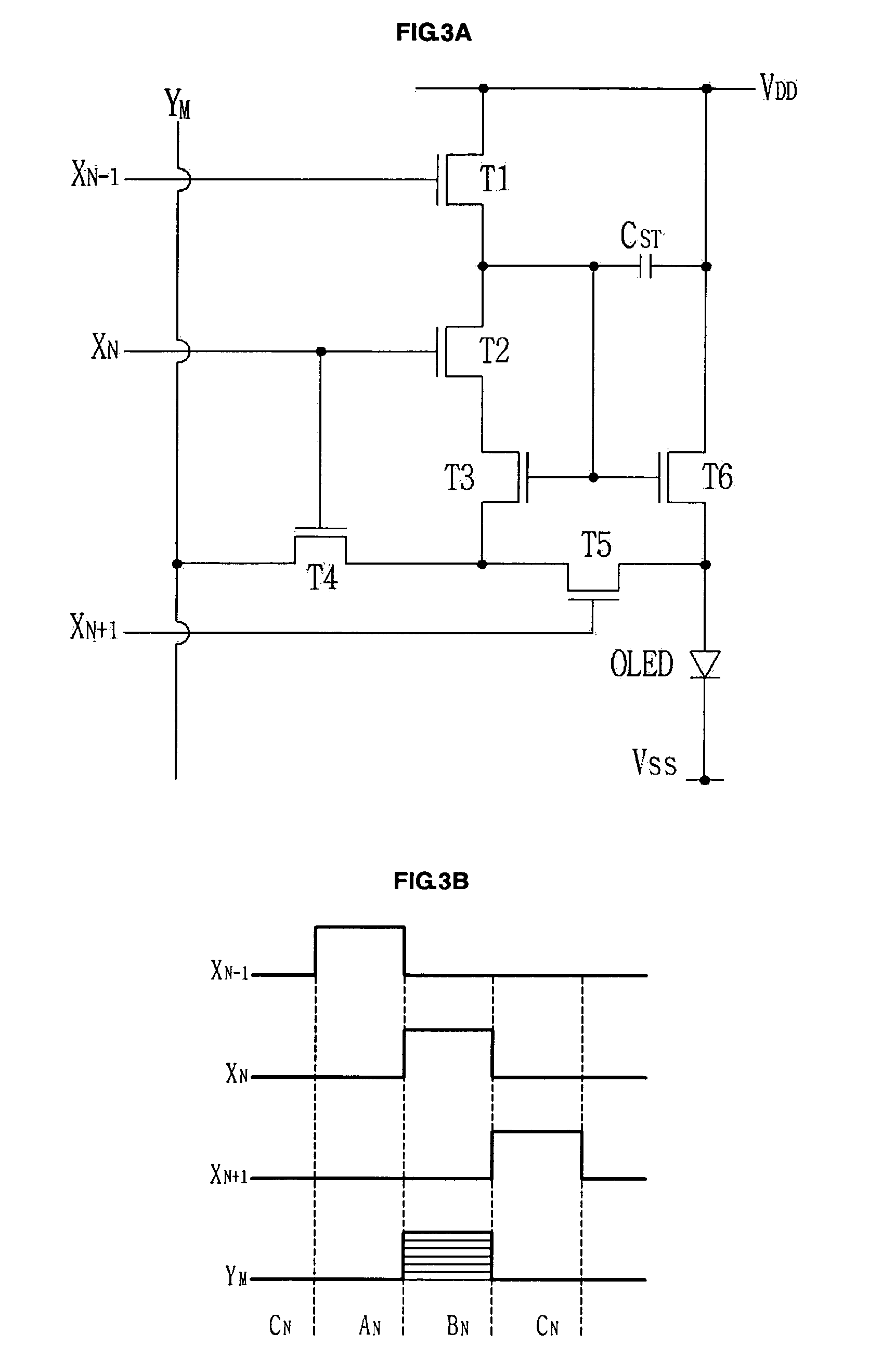
[0046]FIG. 3A is a circuit diagram illustrating a pixel circuit which is included in a driving circuit of an OLED, and FIG. 3B shows waveform of explaining the pixel circuit according to one example embodiment of the present invention.

[0047] According to the example embodiment of the present invention, a driving circuit of an active matrix type OLED enables a voltage filling type of a pixel circuit for filling image information by a voltage to be arranged in a matrix type, similar to the driving circuit of a general OLED.

[0048] The respective pixel circuit may include a scan line driving circuit for transmitting a selecting signal and an unselecting signal to a plurality of scan lines, a data line driving circuit for applying a data voltage to the plurality of data lines, an OLED which is arranged in each intersection that the scan lines and the data lines are intersected and which emits light by a driving current, and a plurality of transistors for applying a desired current to t...

example 2

[0074]FIG. 4A shows a pixel circuit which is included in the driving circuit of the OLED according to another example embodiment of the present invention, and FIG. 4B shows waveform for explaining the pixel circuit.

[0075] According to the embodiment of the present invention, a driving circuit of an active matrix type OLED enables a voltage filling type of a pixel circuit for filling image information by a voltage to be arranged in a matrix type, similar to the driving circuit of a general OLED.

[0076] The respective pixel circuit may include a scan line driving circuit for transmitting a selecting signal and an unselecting signal to a plurality of scan lines, a data line driving circuit for applying a data voltage to the plurality of data lines, an OLED which is arranged in each intersection that the scan lines and the data lines are intersected and which emits light by a driving current, and a plurality of transistors for applying a desired current to the OLED.

[0077] As shown in ...


PUM


Abstract

Disclosed are driving circuit and method which are used in an Organic Light Emitting Diode (OLED), and more specifically to a driving circuit of an organic light emitting diode and a driving method thereof which use a thin film transistor (TFT) as an active device. The driving circuit and method can uniformly produce luminance of the light emitting element because the driving current is produced by compensating the unevenness of threshold voltage of the active device. Further, the variance of the threshold voltage Vth due to deterioration of the transistor produced according as the driving circuit of the OLED is utilized for a long time is also compensated, thereby increasing life of the display device which applies the driving circuit of the OLED.

Description

CLAIM FOR PRIORITY [0001] This application claims priority to Korean Patent Application No. 10-2005-0030050 filed on Apr. 11, 2005, in the Korean Intellectual Property Office (KIPO), the entire contents of which are hereby incorporated by reference. BACKGROUND [0002] 1. Field of the Invention [0003] Example embodiments of the present invention relates in general to the field of a driving circuit and method which are used in an Organic Light Emitting Diode (OLED), and more specifically to a driving circuit of an organic light emitting diode and a driving method thereof which can use a thin film transistor (TFT) as an active device. [0004] 2. Description of the Related Art [0005] An Organic Light Emitting Diode (hereafter referred to an OLED) display device is a self-light emitting display device which displays images by electrically exciting a luminescent organic component to emit light, and has an advantage of a low driving voltage, a thin-film, and the like. A Liquid Crystal Displa...

Claims


Application Information

Patent Timeline
Patent Type & Authority Applications(United States)
IPC IPC(8): G09G3/30
CPCG09G3/3233G09G3/3291G09G2300/0819G09G2320/043G09G2310/0251G09G2310/0262G09G2320/0233G09G2300/0842A01G3/02A01G2003/023
Inventor JANG, JINCHOI, JAE-WON
Owner SILICON DISPLAY TECH CO LTD
Why Eureka
Try Eureka