
Wavelength division multiplexed light source and passive optical network using the same

a technology of multiplexing light source and optical network, applied in multiplex communication, instruments, optical elements, etc., can solve the problems of increasing the cost of realizing the optical network using the dense wavelength division multiplexer, increasing the cost of realizing the optical network, and increasing the cost of arranging the waveguide grating,

Inactive Publication Date: 2006-10-19
SAMSUNG ELECTRONICS CO LTD
View PDF3 Cites 12 Cited by
  • Summary
  • Abstract
  • Description
  • Claims
  • Application Information

AI Technical Summary

Benefits of technology

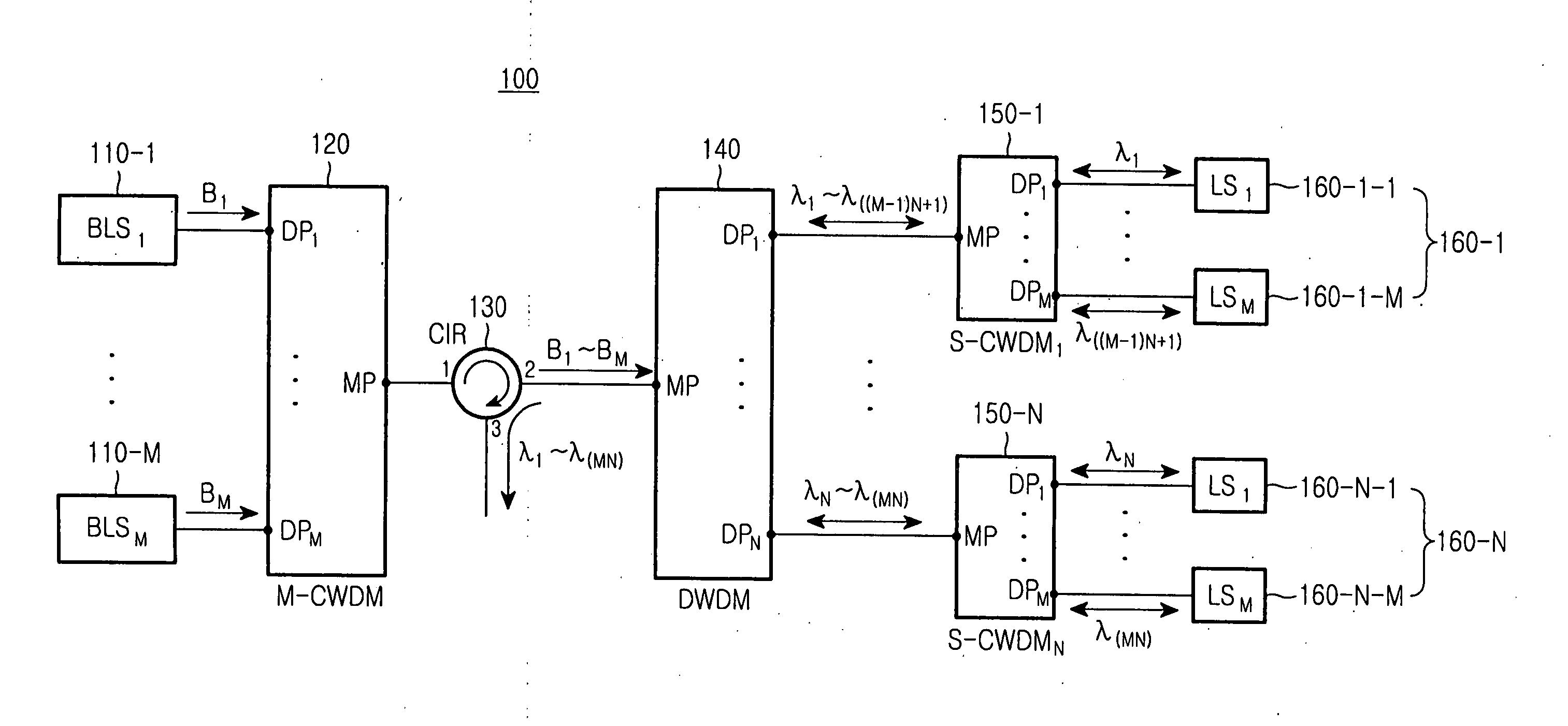
The present invention provides a wavelength division multiplexed light source and a passive optical network that can economically accommodate a large number of subscribers. The light source includes a dense wavelength division multiplexer that spectrally divides lights into multiple channels, which are separated by a wavelength period. The network includes a central office outputting multiplexed optical signals, which are then demultiplexed at a remote node using secondary coarse wavelength division multiplexers and external light injection type light sources. The demultiplexed optical signals are then detected by a subscriber side apparatus. The technical effects of the invention include improved cost-effectiveness and increased flexibility in accommodating a large number of subscribers.

Problems solved by technology

Point to point connections of the central office and each subscriber device would require too many optical fibers.
The arranged waveguide grating, which is a representative material used for the wavelength division multiplexer, is still expensive.
Therefore, when the wavelength division multiplexer included in the wavelength division multiplexed light source is made to be highly dense in order to increase the maximum number of subscribers, the cost of realizing the dense wavelength division multiplexer increases and the cost of realizing the optical network using the dense wavelength division multiplexer also increases.
As described above, it is costly to manufacture the conventional wavelength division multiplexed light source and the optical network using the same.

Method used


Image

  • Wavelength division multiplexed light source and passive optical network using the same
  • Wavelength division multiplexed light source and passive optical network using the same
  • Wavelength division multiplexed light source and passive optical network using the same

Examples


first embodiment

[0040]FIG. 7 provides, by way of illustrative and non-limitative example, a passive optical network using a wavelength division multiplexing scheme according to the present invention. The passive optical network 300 includes a central office 310, remote node 390 connected to the central office 310 through trunk optical fibers 380, and subscriber side apparatus 430 connected to the remote node 390 through distributed optical fibers of the first, second, third, . . . , Nth groups 420-1, 420-2, 420-3, . . . , 420-N.

[0041] The central office 310 includes the first, second, third, . . . , Mth broadband light sources 320-1, 320-2, 320-3, . . . , 320-M; a main coarse wavelength division multiplexer (M-CWDM) 330; an optical circulator (CIR) 340; a dense wavelength division multiplexer (DWDM) 350; the first, second, third, . . . , Nth secondary coarse wavelength division multiplexer (S-CWDM) 360-1, 360-2, 360-3, 360-N; and external light injection type light sources 370-1-1, 370-1-2, 370-1-3...

second embodiment

[0053]FIG. 8 shows, by way of example, a passive optical network using a wavelength division multiplexed scheme according to the present invention. The passive optical network 500 includes a central office 510; a remote node 600 connected to the central office 510 through a trunk optical fiber 590; and a subscriber side apparatus 640 connected to the remote node 600 through distributed optical fibers 630-1, 630-2, 630-3, . . . , 630-N of the first, second, third, . . . , and Nth groups. In FIG. 8, a broken line is used to depict light, channel, and optical signal of an upstream wavelength band, and a solid line depicts light, channel and optical signal of a downstream wavelength band.

[0054] The central office 510 includes first, second, third, . . . , Mth downstream broadband light sources 520-1, 520-2, 520-3, . . . , 520-M; first, second, third, . . . , Mth upstream broadband light sources 530-1, 530-2, 530-3, . . . , 530-M; first and second main coarse wavelength division multiple...


PUM


Abstract

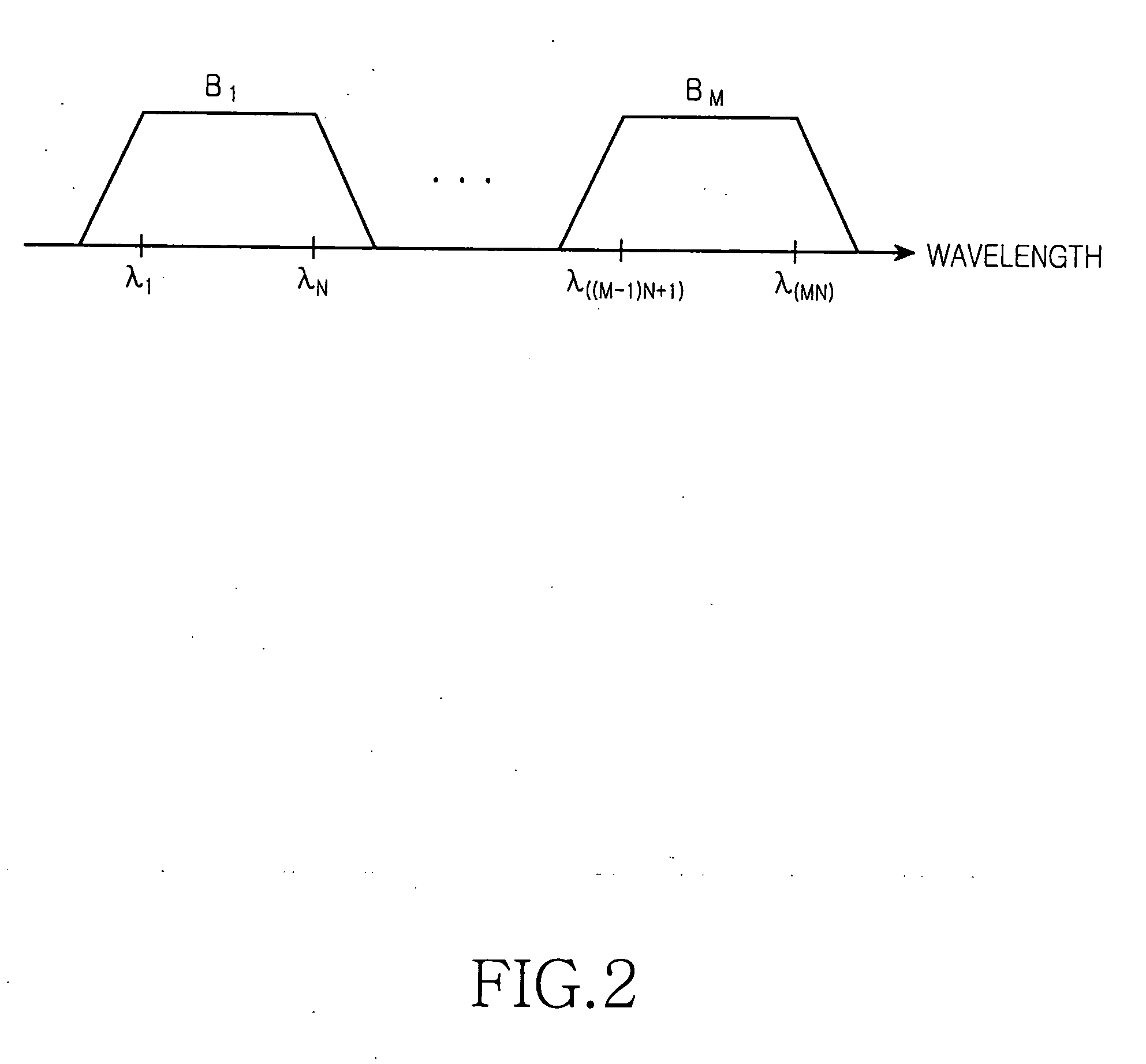
A wavelength division multiplexed light source for a passive optical network using the same includes broadband light sources arranged at a desired interval on a wavelength axis, so as to output wavelength bands each having a plurality of structural wavelengths. Further included is a main coarse wavelength division multiplexer (M-CWDM) for multiplexing the lights and a dense wavelength division multiplexer (DWDM) for spectrally dividing the multiplexed light into the channels corresponding to structural wavelengths of the multiplexed light. Groups are consequently generated each of which has a plurality of channels spaced at wavelength period.

Description

CLAIM OF PRIORITY [0001] This application claims priority to an application entitled “Wavelength Division Multiplexed Light Source and Passive Optical Network Using the Same,” filed with the Korean Intellectual Property Office on Apr. 18, 2005 and assigned Serial No. 2005-0031949, the contents of which are incorporated herein by reference. BACKGROUND OF THE INVENTION [0002] 1. Field of the Invention [0003] The present invention relates to a passive optical network, and more particularly to a wavelength division multiplexed light source and a passive optical network using the same. [0004] 2. Description of the Related Art [0005] An optical network of current interest includes a central office to which subscriber devices are connected by optical fibers so as to provide various broadband services. Point to point connections of the central office and each subscriber device would require too many optical fibers. Therefore, it is general practice to install remote nodes near the subscribe...

Claims


Application Information

Patent Timeline
Patent Type & Authority Applications(United States)
IPC IPC(8): H04J14/02H04B10/00H04J14/00
CPCH04B10/506H04J14/02H04J14/0226H04J2014/0253H04J14/0282H04J14/0246H04J14/025H04J14/0227H04B10/2581G02B6/293
Inventor SHIN, DONG-JAEHWANG, SEONG-TAEKJUNG, DAE-KWANG
Owner SAMSUNG ELECTRONICS CO LTD
Learn More