Thread mill having flute twisting in direction opposite to rotating direction

US20060233623A1Active Publication Date: 2006-10-19OSG

Image

  • Thread mill having flute twisting in direction opposite to rotating direction
  • Thread mill having flute twisting in direction opposite to rotating direction
  • Thread mill having flute twisting in direction opposite to rotating direction

Examples


Embodiment Construction

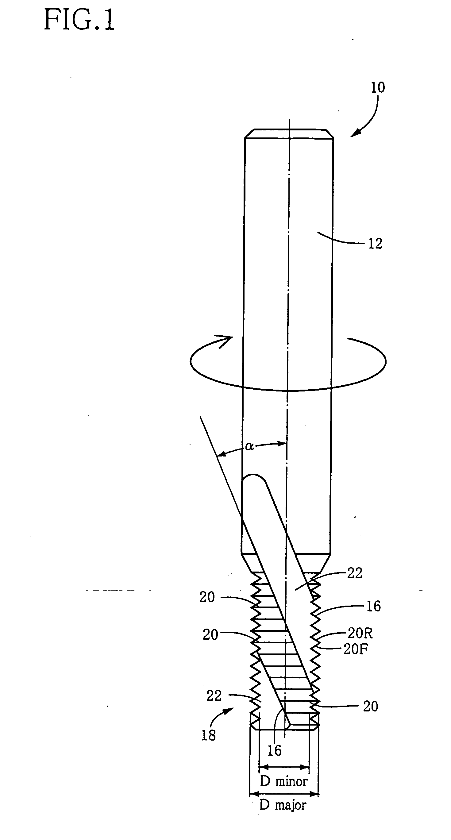
[0036] Referring first to FIG. 1, there will be described a thread mill 10 that is constructed according to an embodiment of the invention. The thread mill 10 includes: a cylindrical shank 12 that is to be attached through a suitable holder to a main spindle of a machine tool such as a machining center; and a cylindrical main body in the form of a fluted main body 18 that is coaxial and formed integrally with the shank 12. The fluted main body 18 has a multiplicity of annular protrusions 20 formed on its outer circumferential surface and arranged in axial direction of the main body 18 at a pitch between each adjacent pair of the annular protrusions 20 corresponding to a pitch of an internal thread 30 (see FIG. 2) that is to be machined by the thread mill 10. Each of the annular protrusions 20 has a profile of each ridge of the internal thread 30. Unlike a helical protrusion provided in a tap, each annular protrusion 20 of the thread mill 10 extends in a circumferential direction of ...


PUM

PropertyMeasurementUnit
Angleaaaaaaaaaa
Angleaaaaaaaaaa
Diameteraaaaaaaaaa

Abstract

A thread mill that is to be moved along a helical interpolation path while being rotated about an axis of the thread mill in a rotating direction, for forming a thread in a circumferential surface of a workpiece. The thread mill includes a cylindrical main body having (a) at least one spiral flute formed in an outer circumferential surface of the cylindrical main body, and (b) at least one cutting edge each provided by a rear-side one of widthwise opposite edges, as viewed in the rotating direction, of a corresponding one of the at least one spiral flute. Each of the at least one spiral flute extends in a direction opposite to the rotating direction as viewed in a direction away from a proximal end of the cylindrical main body toward a distal end of the cylindrical main body. Also disclosed is a method of forming the thread by using the thread mill.

Description

BACKGROUND OF THE INVENTION [0001] 1. Field of the Invention [0002] This invention relates in general to a thread mill for forming an external or internal thread in an outer or inner circumferential surface of a workpiece, and more particularly to such a thread mill that is capable of forming the thread without undesirable debris or burrs being left on the threaded circumferential surface. [0003] 2. Discussion of the Related Art [0004] As a kind of tool for forming an internal thread in an inner circumferential surface of a hole previously formed in a workpiece, there is known a thread mill including a cylindrical main body having annular protrusions formed on its outer circumferential surface. Each of the annular protrusions has a profile of each ridge of the internal thread that is to be formed, and extends in a circumferential direction of the cylindrical main body without extending in an axial direction of the cylindrical main body for providing no lead. The cylindrical main bod...

Claims


Application Information

Patent Timeline
19 Oct 2006
Publication
US20060233623A1
IPC
B23C3/32; B23C5/10
CPC
B23G1/32; B23G5/18; B23G2200/48; Y10T409/30056; Y10T407/1948; Y10T407/172; Y10T409/300112
Inventors
ANDOH, HARUYASU; NAKAJIMA, TAKAYUKI