Method and apparatus for measuring fiber orientation of a moving web

a technology of moving webs and fibers, applied in the direction of instruments, papermaking, image enhancement, etc., can solve the problems of dimensional instability, twisting, curling, skewing, and defective products, and achieve the effect of robust estimation of the statistical distribution of fibers

Active Publication Date: 2006-10-26
HONEYWELL INT INC
View PDF34 Cites 40 Cited by
  • Summary
  • Abstract
  • Description
  • Claims
  • Application Information

AI Technical Summary

Benefits of technology

[0015] The present invention is based in part on the development of an image-based measurement technique that directly measures the orientation of fibers in a moving web that comprises nonwoven material. The technique is capable of measuring a larger area of the web, e.g., paper, than is possible with the spot illumination methods, and thus produces a measurement which is more representative of the web. Moreover, by measuring the orientation angles of the individual fibers, a more robust estimate of the statistical distribution of fibers is obtained.

Problems solved by technology

In particular, if the fiber orientation distribution is incorrect, then dimensional instability in the form of twist, curl, and skew will occur, and strength axes will not correspond to manufacture axes.
This leads to defective products such as paper that jams in printers / copiers, packaging that jams in discrete item containers, and boxes which lean or collapse when stacked.
Because the spot illumination area is relatively small, these techniques do not necessarily yield representative measurements for the sheet.
This laboratory process is labor-intensive and not applicable to on-line measurements of moving webs.
Therefore, despite the asserted advantages associated with these fiber orientation measurement systems, none of these apparatuses affords a simple, robust, and accurate device for on-line fiber orientation measurements of a moving web or sheet made of nonwoven components.

Method used


Image

  • Method and apparatus for measuring fiber orientation of a moving web
  • Method and apparatus for measuring fiber orientation of a moving web
  • Method and apparatus for measuring fiber orientation of a moving web

Examples


Embodiment Construction

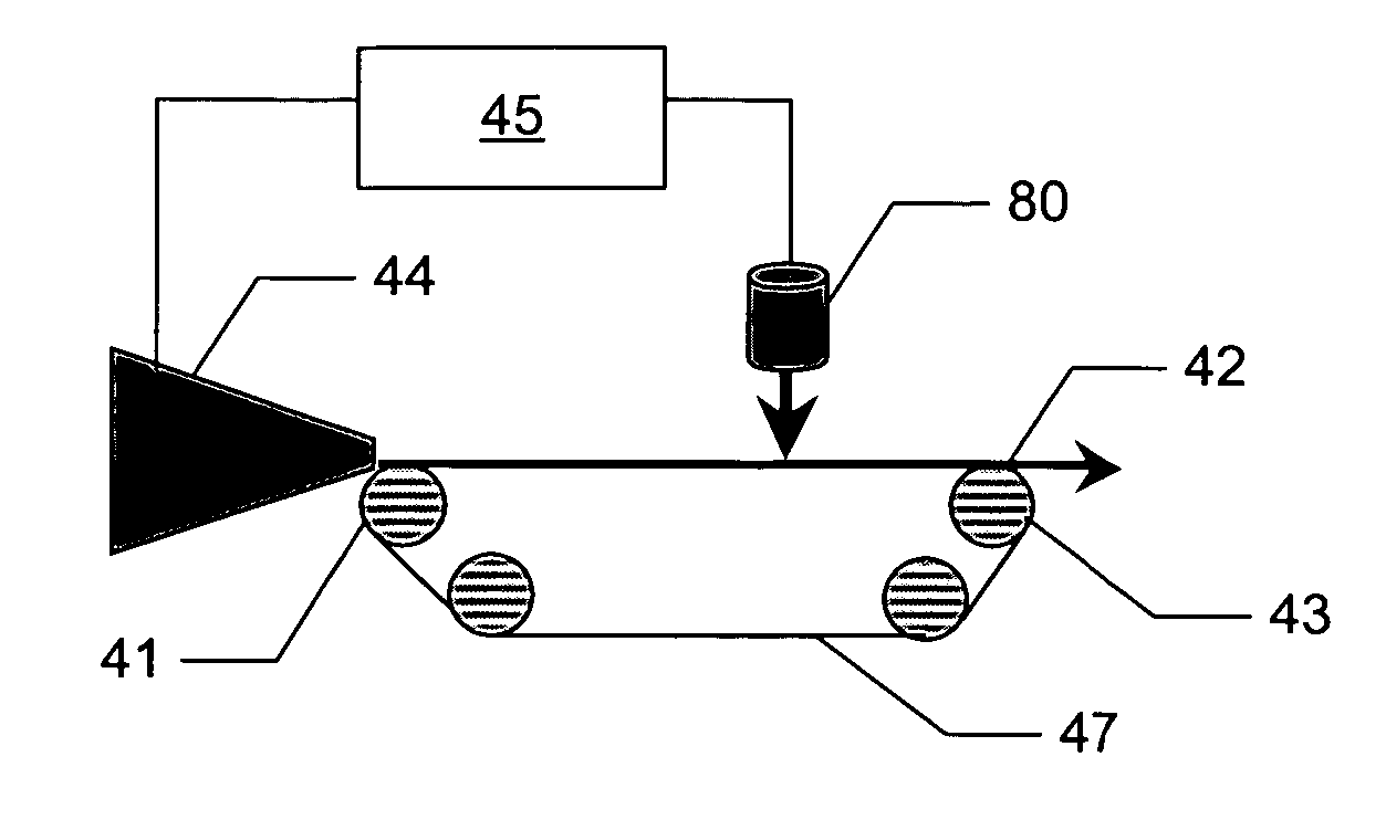
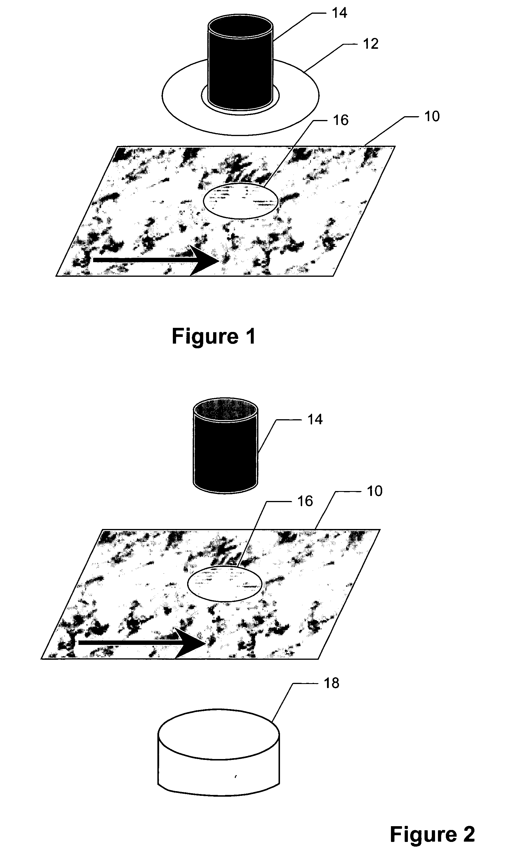
[0034] The present invention relates to methods and devices for directly measuring the fiber orientation in nonwoven materials especially where the material is in the form of a moving web, film or sheet. The fiber orientation of the whole thickness of the web or just the surface of the web can be measured. The fiber orientation measurements can be expressed as one or more different parameters that are used in controlling the papermaking process and / or characterizing the properties of the product. The parameters include, for instance: average fiber orientation angle, fiber orientation anisotropy index, and statistical distribution of fiber orientation angles. In addition, the fiber orientation measurements from both sides of the web can yield information regarding curl and twist deformations of the web, e.g., paper.

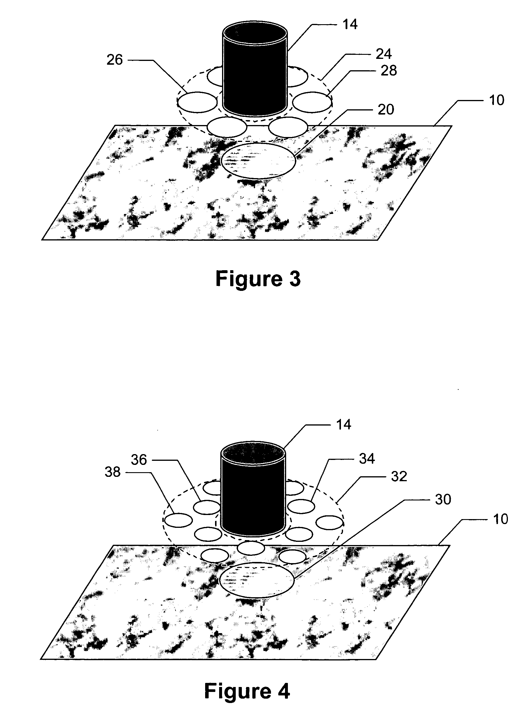
[0035] The analysis method employs fractional-order gradients that are evaluated on at least two preferably orthogonal axes at a plurality of loci in the digital images o...


PUM

PropertyMeasurementUnit
widthaaaaaaaaaa
angleaaaaaaaaaa
diameteraaaaaaaaaa

Abstract

An image-based measurement technique that directly measures the orientation of fibers in a moving web that comprises nonwoven material measures the orientation angles of the individual fibers so that a more robust estimate of the statistical distribution of fibers is obtained. The technique includes the steps of: (a) illuminating an area on at least one side of the web with radiation; (b) obtaining at least one digital image of the illuminated area; and (c) calculating the fiber orientation of the web by processing the at least one digital image with a gradient operator thereby analyzing the distribution of observed fiber orientation angles within the image. The gradient operator is preferably of a non-integer order between ⅓ and ⅔ and particularly between ¼ and ¾. The use of fractional-gradient operators yields more reliable results than when integer order gradients are employed.

Description

FIELD OF THE INVENTION [0001] The present invention is directed to techniques of determining the fiber orientation in webs formed from nonwoven materials and particularly to image-based measurements of the average fiber orientation of paper by on-line image analysis. BACKGROUND OF THE INVENTION [0002] In the manufacture of paper on continuous papermaking machines, a web of paper is formed from an aqueous suspension of fibers (stock) on a traveling mesh, papermaking fabric, or wire and water drains by gravity and suction through the fabric. The web is then transferred to the pressing section where more water is removed by pressure and vacuum. The web next enters the dryer section where steam heated dryers and hot air completes the drying process. The paper machine is, in essence, a water removal, system. A typical forming section of a papermaking machine includes an endless traveling papermaking fabric or wire, which travels over a series of water removal elements such as table rolls...

Claims


Application Information

Patent Timeline
Patent Type & Authority Applications(United States)
IPC IPC(8): D21F11/00G01N21/84
CPCG01N21/8806G01N21/8851G06T2207/30124G01N2021/8681G06T7/0048G01N21/898G06T7/77
Inventor SHAKESPEARE, JOHN F.KELLOMAKI, MARKKU M.
Owner HONEYWELL INT INC
Why Eureka
Try Eureka