Ion generation by the temporal control of gaseous dielectric breakdown

a dielectric breakdown and temporal control technology, applied in the field of producing ions and free electrons in gaseous dielectric breakdown with electric current pulse, can solve the problems of gas breakdown and transition from electrical insulator to conductor, inability to produce a large number of ions, contamination and damage of nano-featured cathode emitters, etc., to prevent the formation of destructive plasma or glow, and stop the breakdown of gas

Active Publication Date: 2006-10-26
VENTIVA
View PDF17 Cites 11 Cited by
  • Summary
  • Abstract
  • Description
  • Claims
  • Application Information

AI Technical Summary

Benefits of technology

[0014] The present invention relates to a method and apparatus for ion generation wherein an ionization process is controlled temporally so as to halt the breakdown of the gas and prevent the formation of a destructive plasma or glow. According to one aspect, the present invention recognizes the time evolution of gaseous dielectric breakdown to create ions at near ambient conditions. Dielectric breakdown is initiated by exposing the gas to an electric field that exceeds its breakdown strength. Avalanches of electrons sweep across the gas, creating ions. After a short time, the electric field is reduced below the breakdown strength, stopping the electron avalanches and the breakdown process and preventing the gas from becoming a glow or plasma. The gas is now filled with ions at near ambient conditions. The ions are directed by a secondary electric field or by other means to be used for any of the aforementioned purposes. Some of many advantages of this ion generation mechanism are its simplicity and its ability to create ions with a relatively small voltage at ambient temperature and pressure.

Problems solved by technology

However, there is a point where the potential difference between two electrodes can be high enough to cause the gas to breakdown and transition from an electrical insulator to a conductor.
The disadvantages of this approach include a sensitivity of the nano-featured cathode emitter to contamination and damage, and an inability to produce a large enough number of ions.
Electrodes are exposed to the hostile environment of a high-temperature plasma and suffer from degradation effects.
Ions generated by the prior art are not suited for various applications such as cooling systems because, for example, introducing ions at a high temperature would limit or eliminate the heat removal ability of such a system.

Method used


Image

  • Ion generation by the temporal control of gaseous dielectric breakdown
  • Ion generation by the temporal control of gaseous dielectric breakdown
  • Ion generation by the temporal control of gaseous dielectric breakdown

Examples


Embodiment Construction

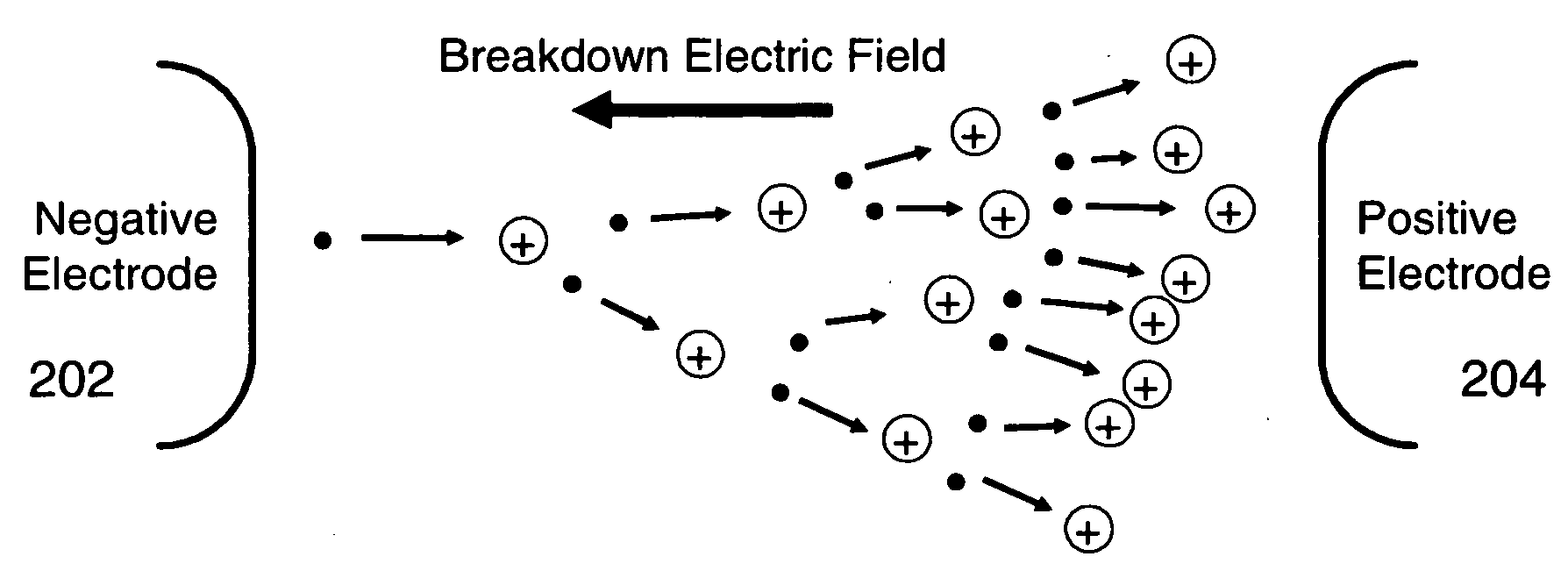
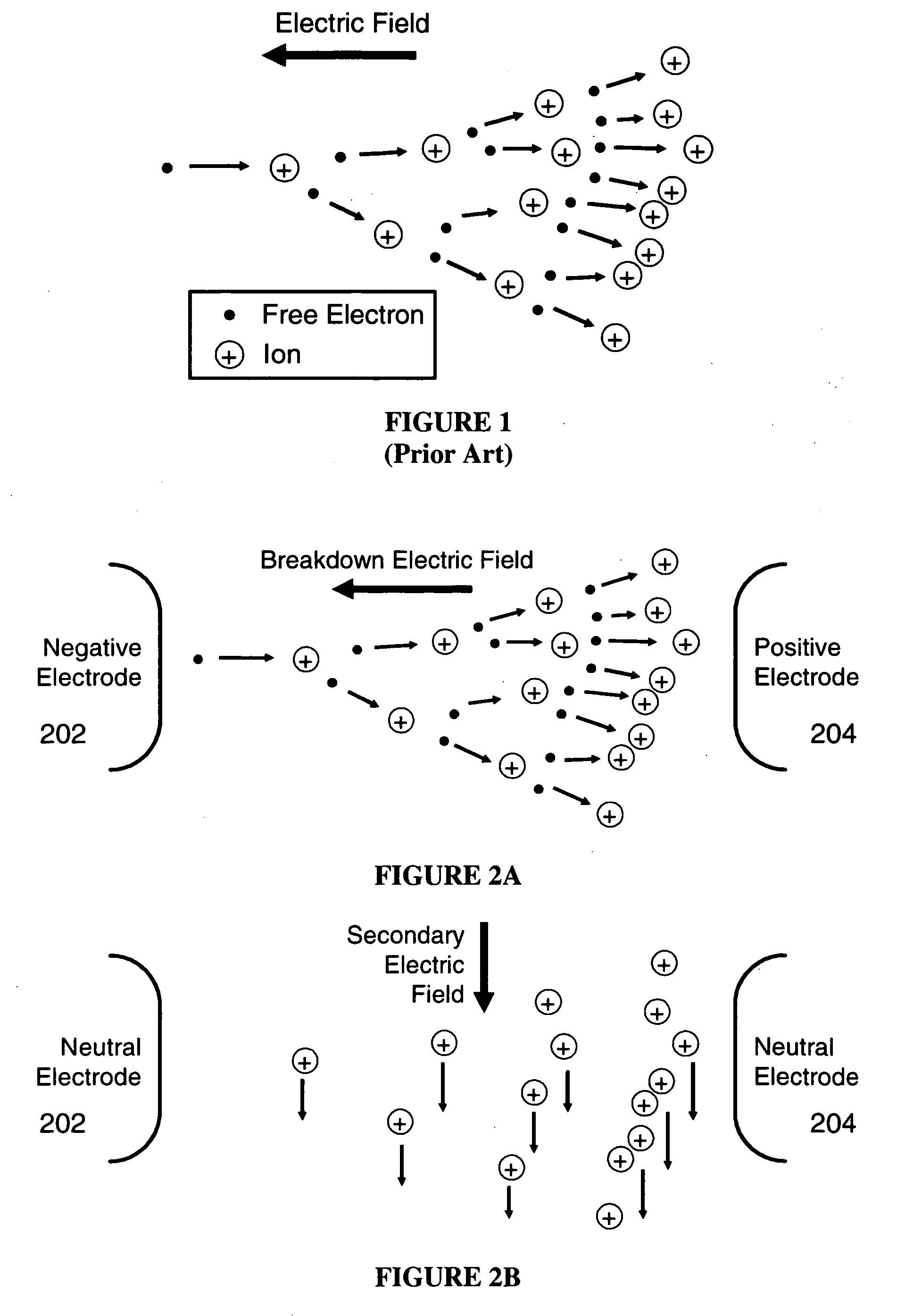
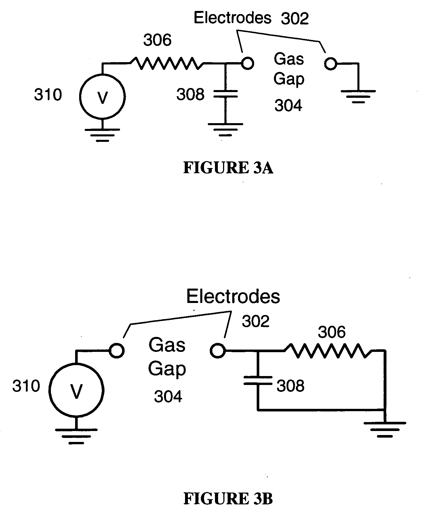
[0024] The present invention will now be described in detail with reference to the drawings, which are provided as illustrative examples of the invention so as to enable those skilled in the art to practice the invention. Notably, the figures and examples below are not meant to limit the scope of the present invention to a single embodiment, but other embodiments are possible by way of interchange of some or all of the described or illustrated elements. Moreover, where certain elements of the present invention can be partially or fully implemented using known components, only those portions of such known components that are necessary for an understanding of the present invention will be described, and detailed descriptions of other portions of such known components will be omitted so as not to obscure the invention. In the present specification, an embodiment showing a singular component should not be considered limiting; rather the invention can be extended to other embodiments inc...


PUM


Abstract

An apparatus and method for ion generation are adapted such that an ionization process is controlled temporally, to first initiate, then to halt the breakdown of the gas before a destructive plasma or glow is formed. This method controls the release of energy to the gas in such a manner as to create ions but prevent the heating of the gas. The primary advantages of this ion generation mechanism are its simplicity, efficiency and its ability to create ions at ambient temperature and pressure.

Description

CROSS-REFERENCE TO RELATED APPLICATIONS [0001] The present application is based on, and claims priority from, U.S. Provisional Appln. No. 60 / 627,261, filed Nov. 12, 2004, the contents of which are fully incorporated herein by reference.FIELD OF THE INVENTION [0002] The present invention relates to a method for producing ions and free electrons in a gas with an electric current pulse, and more particularly to a method that controls the release of energy to the gas in such a manner as to create ions and free electrons but prevent heating of the gas. BACKGROUND OF THE INVENTION [0003] Ion generation is used in a wide variety of applications including, for example, ion implantation, thin film formation, etching and sputtering operations, propulsion in space ships, electrostatographic devices, electro-static air cleaners, for the generation of negative ions for medicinal purposes and electro-hydrodynamic gas pumps. [0004] As is understood in the field of ion generation, a gas such as air...

Claims


Application Information

Patent Timeline
Patent Type & Authority Applications(United States)
IPC IPC(8): H01T23/00
CPCH01J2237/0815H05H1/24H01T23/00H05H1/46H05H1/2406H05H1/4697H05H2242/22
Inventor SCHLITZ, DANIEL JON
Owner VENTIVA
Why Eureka
Try Eureka