Ultracapacitor audio amplifier

a technology of audio amplifier and amplifier, applied in the field of amplifiers, can solve the problems of introducing noise and distortion into the signal, single transistor not providing sufficient gain, and amplification,

Active Publication Date: 2006-10-26
ROCKFORD CORP A CORP OF AZ
View PDF8 Cites 24 Cited by
  • Summary
  • Abstract
  • Description
  • Claims
  • Application Information

AI Technical Summary

Benefits of technology

[0019] A preferred embodiment of the present invention is an amplifier that employs ultracapacitors. Ultracapacitors have storage capacities on the order of several farads with storage times of several seconds. The amplifier uses power from a primary power source on an averaging basis to amplify a signal. When the amplifier requires less than this average power level to amplify the signal, the excess power used from the primary power supply is used to charge the ult

Problems solved by technology

This process invariably introduces some noise and distortion into the signal, and the process is not completely efficient.
For many purposes a single transistor does not provide sufficient gain, or amplification.
They are not very efficient—a theoretical maximum of 50% efficiency is obtainable, but for small signals, this waste of power is small and tolerable.
Because the device is always conducting, even if there is no input at all, power is wasted.
This is the reason for its inefficiency.
Historically, valve amplifiers often used a Class A power amplifier simply because valves are large and expensive; the Class A design uses only a single device.
This design increases operating efficiency, but suf

Method used


Image

  • Ultracapacitor audio amplifier
  • Ultracapacitor audio amplifier
  • Ultracapacitor audio amplifier

Examples


Embodiment Construction

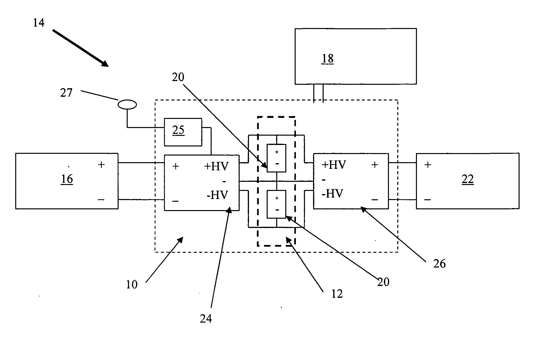
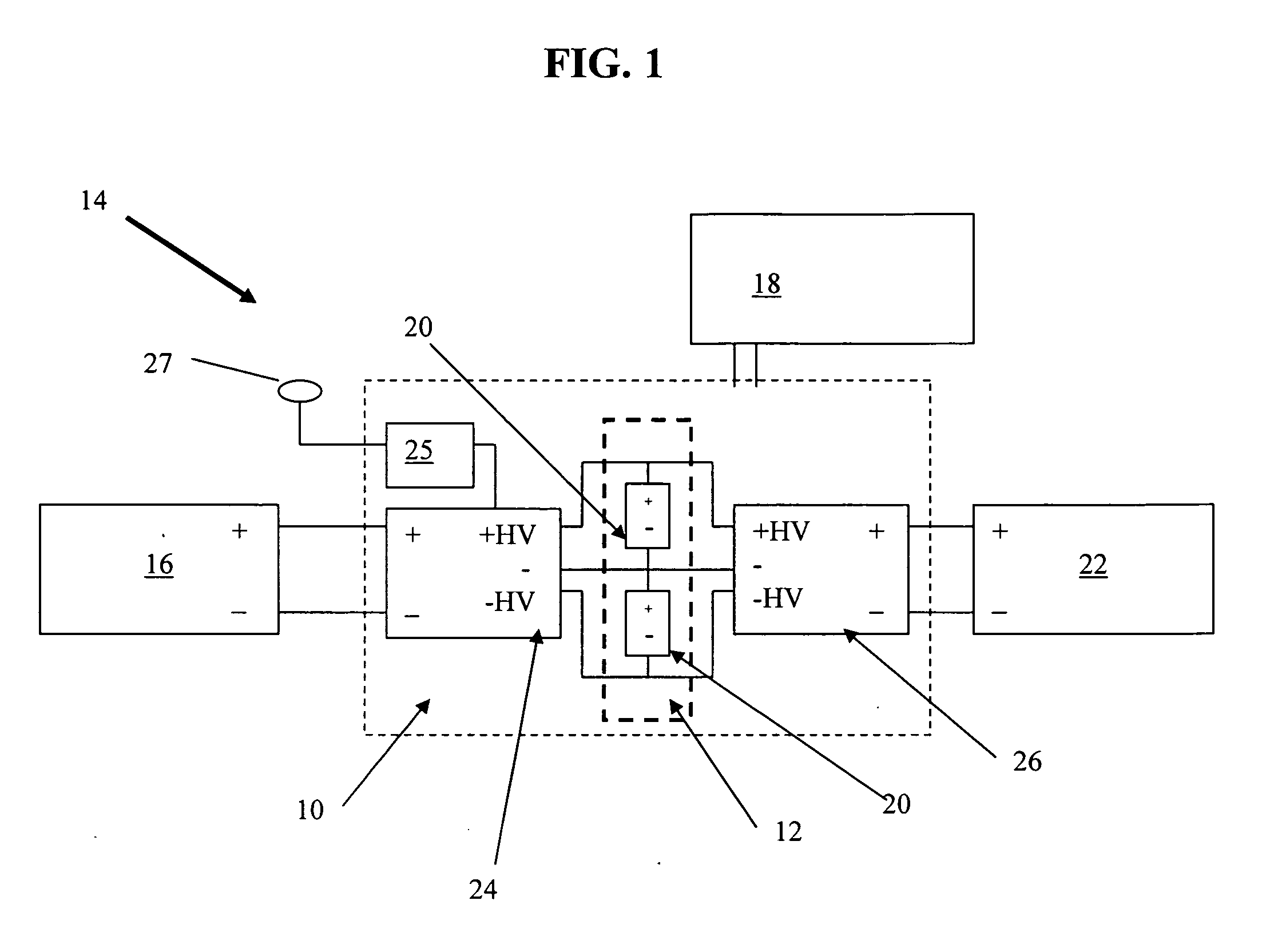
[0024] Referring to the Figures by characters of reference, FIG. 1 illustrates a block diagram of an amplifier 10 having an ultracapacitor power supply 12 coupled with an electrical system 14 that includes primary power supply 16. Amplifier 10 may accept a varying input signal from signal source 18 and produces an output signal that varies in the same way as the input, but with a larger amplitude. Primary power supply 16 is configured to provide a level of power sufficient to supply at least the average power of the amplified output signal from amplifier 10.

[0025] Amplifier 10 includes an ultracapacitor power supply 12 that compliments primary power supply 16. Ultracapacitor power supply 12 includes a pair of ultracapacitors 20 in a parallel configuration. The use of two ultracapacitors 20 in a parallel configuration is merely exemplary. Ultracapacitor power supply 12 may include any number of ultracapacitors 20 in either serial, parallel, or hybrid configurations. In addition, ult...


PUM


Abstract

An amplifier that employs ultracapacitors to accommodate the peak power needs of an electrical system, such as car audio system. The amplifier operates off of a primary power source for average signal power levels and then uses the ultracapacitors when operating at peak power levels. As such, the amplifier can operate off of a primary power supply that supplies less than the peak power required by the amplifier.

Description

FIELD OF THE INVENTION [0001] The present invention relates to the field of amplifiers, and more specifically to amplifiers configured to include ultracapacitors for power storage. BACKGROUND OF THE INVENTION [0002] Amplifiers are devices that accept a varying input signal and produce an output signal that varies in the same way as the input, but with a larger amplitude. The input and output signals may consist of a current, a voltage, a mechanical motion, or any other signal. An electronic amplifier is a device for increasing the power of a signal. It does this by taking power from a power supply and shaping the output to match the input signal. This process invariably introduces some noise and distortion into the signal, and the process is not completely efficient. Amplifiers always produce some waste as heat. [0003] Different designs of amplifiers are used for different types of applications and signals. Amplifiers broadly fall into three categories: small signal amplifiers, low ...

Claims


Application Information

Patent Timeline
IPC IPC(8): H03F3/04
CPCH03F3/20
Inventor D'AMORE, ANTHONY THOMAS
Owner ROCKFORD CORP A CORP OF AZ
Why Eureka
Try Eureka