Radiological imaging apparatus and cooling method of same

Inactive Publication Date: 2006-10-26
HITACHI LTD
View PDF4 Cites 29 Cited by
  • Summary
  • Abstract
  • Description
  • Claims
  • Application Information

AI Technical Summary

Benefits of technology

[0017] Signals from a plurality of detector boards are processed by one signal processing board via the intermediate board, whereby signals from a plurality of detector boards can be covered by one signal processing board, thus increasing a degree of freedom of design.
[0018] The cooling method of the radiological imaging apparatus of the present invention comprises a step of separating the detector space in which the radiation detectors on the unit board are placed and the signal processing circuit space in which the signal processing circuit is placed, from each other, by the partition wall type intermediate board, and feeding a coolant to the signal processing circuit space. According to this method, the signal processing circuit space in which the signal processing circuit is placed can be cooled b

Problems solved by technology

The scintillator has a disadvantage that its energy resolution is low and an accurate diagnosis cannot necessarily be performed because the number of photons generated during conversion into visible light is small, and in addition, two-stage conversion processes are required as described above.
Particularly, the deterioration in energy resolution is a cause of impossibility of quantitative evaluation during 3D imaging in the PET.
However, in a situation in which with enhancement of the performance of the radiological imaging apparatus, the

Method used


Image

  • Radiological imaging apparatus and cooling method of same
  • Radiological imaging apparatus and cooling method of same
  • Radiological imaging apparatus and cooling method of same

Examples


embodiment 1

[Embodiment 1]

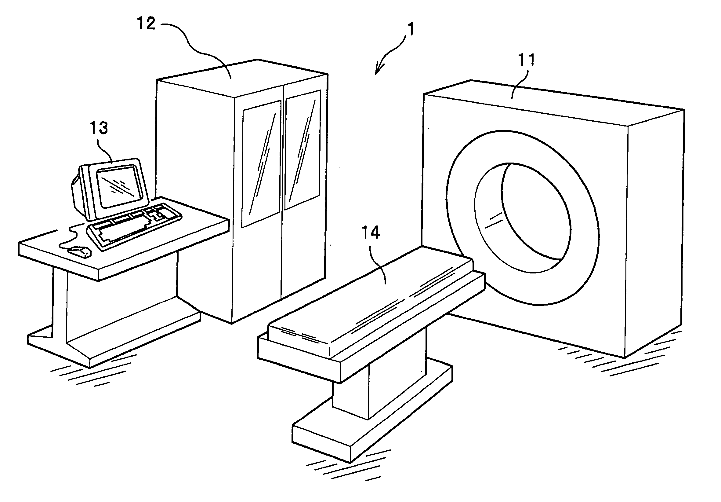
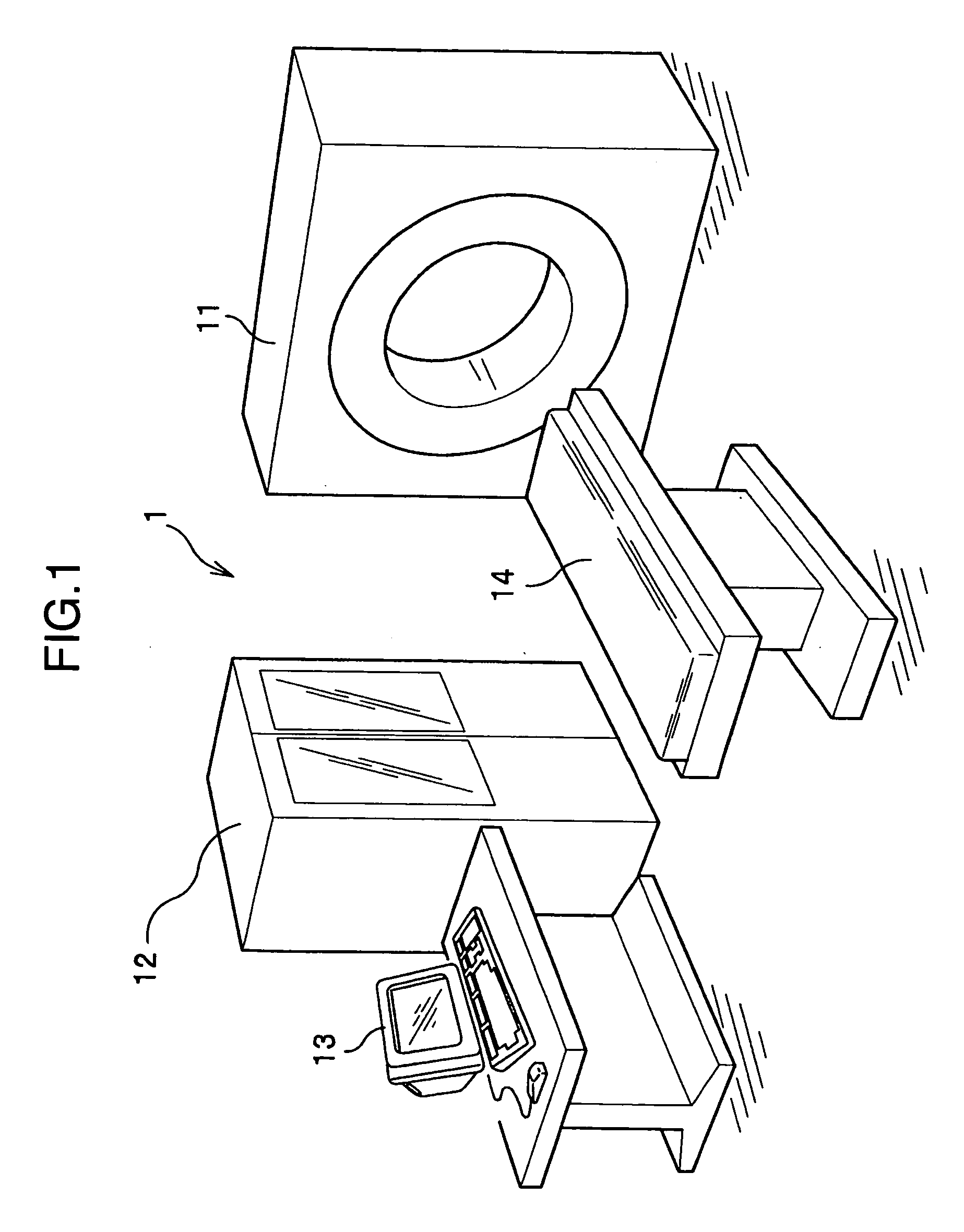
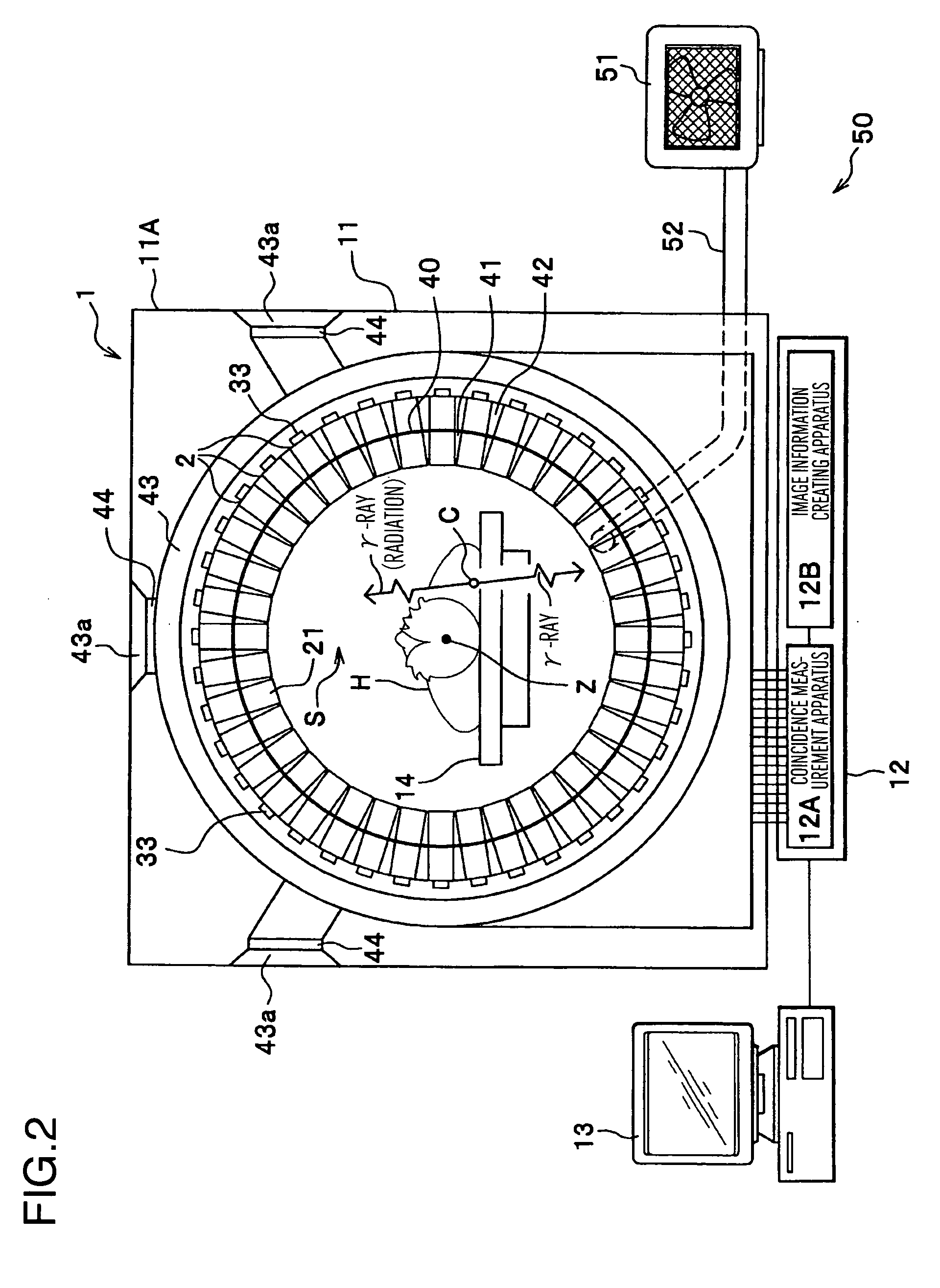
[0032] First, the general configuration of the radiological imaging apparatus (PET apparatus 1) of this embodiment will be described with reference to FIGS. 1 and 2. The PET apparatus 1 comprises an imaging apparatus 11, a data processing apparatus 12 processing detection data obtained by imaging by the imaging apparatus 11 to convert the data into image data, a display apparatus 13 two-dimensionally or three-dimensionally displaying the image data output by the data processing apparatus 12, and a bed 14 forward-and-backward movably supporting a testing subject H (see FIG. 2) in the body axis direction.

[0033] The imaging apparatus 11 comprises detector units 2 having a large number of semiconductor radiation detectors (hereinafter referred to simply as detectors (FIGS. 3(a) and 3(B) and FIG. 4, the same will apply hereinafter), described in detail later) 21. As shown in FIG. 2, the detector units 2 are placed in a casing 11A of the imaging apparatus 11, and are placed...

embodiment 2

[Embodiment 2]

[0104] The PET apparatus 10 as the radiological imaging apparatus which is another embodiment will be described. The radiological imaging apparatus of this embodiment is different from embodiment 1 in that a housing 60 as a housing member for the detector unit 2 is formed to have a size for covering the entire unit board 20 as shown in FIGS. 6(a) and 6(b) and FIG. 7. Specifically, as shown in these figures, the housing 60 has a box-like shape having a bottom part 60a, and has no opening provided in the lower part unlike the housing 30 described in embodiment 1 (see FIGS. 3(a) and 3(b)). Namely, in the housing 60, the detector space A and the signal processing circuit space B separated by the intermediate board 20C are formed. The bottom part 60a and a side part 60b forming the detector space A of the housing 60 is provided with an air hole 61 communicating with the first air passage 41.

[0105] In this embodiment, the lower part of the housing 60 is placed in the first ...


PUM


Abstract

A radiological imaging apparatus which can keep detectors at a low temperature, improve a time resolution and an energy resolution and perform an accurate diagnosis is provided. In the radiological imaging apparatus, an imaging apparatus imaging a testing subject supported by a bed couples a detector board having placed thereon radiation detectors detecting radiations emitted from the testing subject and a signal processing board having placed thereon a signal processing circuit processing detection signals of the radiation detectors via an intermediate board by connectors, and separates a detector space including the radiation detectors and a signal processing circuit space including the signal processing circuit.

Description

BACKGROUND OF THE INVENTION [0001] The present invention relates to a radiological imaging apparatus using radiations, and particularly relates to a radiological imaging apparatus, such as a positron emission computed tomographic apparatus (hereinafter referred to as “PET” apparatus), suitable for performing a radiographic inspection, and a cooling method of the radiological imaging apparatus. [0002] An inspection technique using radiations can nondestructively inspect the inside of a testing subject. Particularly, radiographic inspection techniques for human bodies include X-ray CTs, PETs, single photon emission computed tomographic apparatuses (hereinafter referred to as “SPECT” apparatus) and the like. [0003] Any of these techniques is a technique in which the physical quantity of an inspection object is measured as an integral value in a radiation traveling direction, and the integral value is back-projected, whereby the physical quantity of each voxel in the testing subject is ...

Claims


Application Information

Patent Timeline
IPC IPC(8): A61B5/05
CPCG01T1/249A61B6/037G01T1/244G01T1/2985
Inventor YANAGITA, NORIHITOIMAI, TSUTOMUMATSUMOTO, TAKASHIAMEMIYA, KENSUKEUENO, YUUICHIROUSEINO, TOMOYUKI
Owner HITACHI LTD
Why Eureka
Try Eureka