Ultrasonic observation apparatus

a technology of ultrasonic observation and apparatus, which is applied in the field of ultrasonic observation apparatus, can solve the problems of reducing the frame rate and not specifically revealing the aspect of the probe used for extracting frequency components, so as to improve the quality and efficiency of medical diagnosis and improve the frame ra

Inactive Publication Date: 2006-10-26
FUJIFILM HLDG CORP +1
View PDF5 Cites 23 Cited by
  • Summary
  • Abstract
  • Description
  • Claims
  • Application Information

AI Technical Summary

Benefits of technology

[0017] According to the present invention, multi-beam scan is performed by transmitting plural ultrasonic beams substantially simultaneously according to a radial scan method or convex scan method in an ultrasonic endoscope, and therefore, the frame rate can be made higher than in a conventional scan method. Further, according to the present invention, plural ultrasonic beams having different frequencies from one another can be substantially simultaneously transmitted by setting respective frequencies of drive signals with respect to transmission apertures for transmitting the ultrasonic beams. Thereby, ultrasonic image information in which high resolving power is maintained in the shallow part and ultrasonic image information on the deep part can be acquired simultaneously. Therefore, the most appropriate ultrasonic images such as an image, in which plural B-mode images at different focal depths are synthesized, a harmonics image, a Doppler image, a frequency subtraction images, in which tissue properties are expressed, can be displayed according to diagnostic purposes, and the quality and efficiency of medical diagnoses can be improved.

Problems solved by technology

However, in comparison to a scan method of performing scanning with viewing angle of 90° by using a convex ultrasonic transducer array, for example, in the case where conditions of sound ray density, scan depth, and so on are set equal, there is a problem of reduction in frame rate because scan time (frame period) for obtaining an image for one frame becomes longer.
Further, JP-P2001-170046A does not specifically disclose an aspect of a probe to be used for extracting frequency components.

Method used


Image

  • Ultrasonic observation apparatus
  • Ultrasonic observation apparatus
  • Ultrasonic observation apparatus

Examples


first embodiment

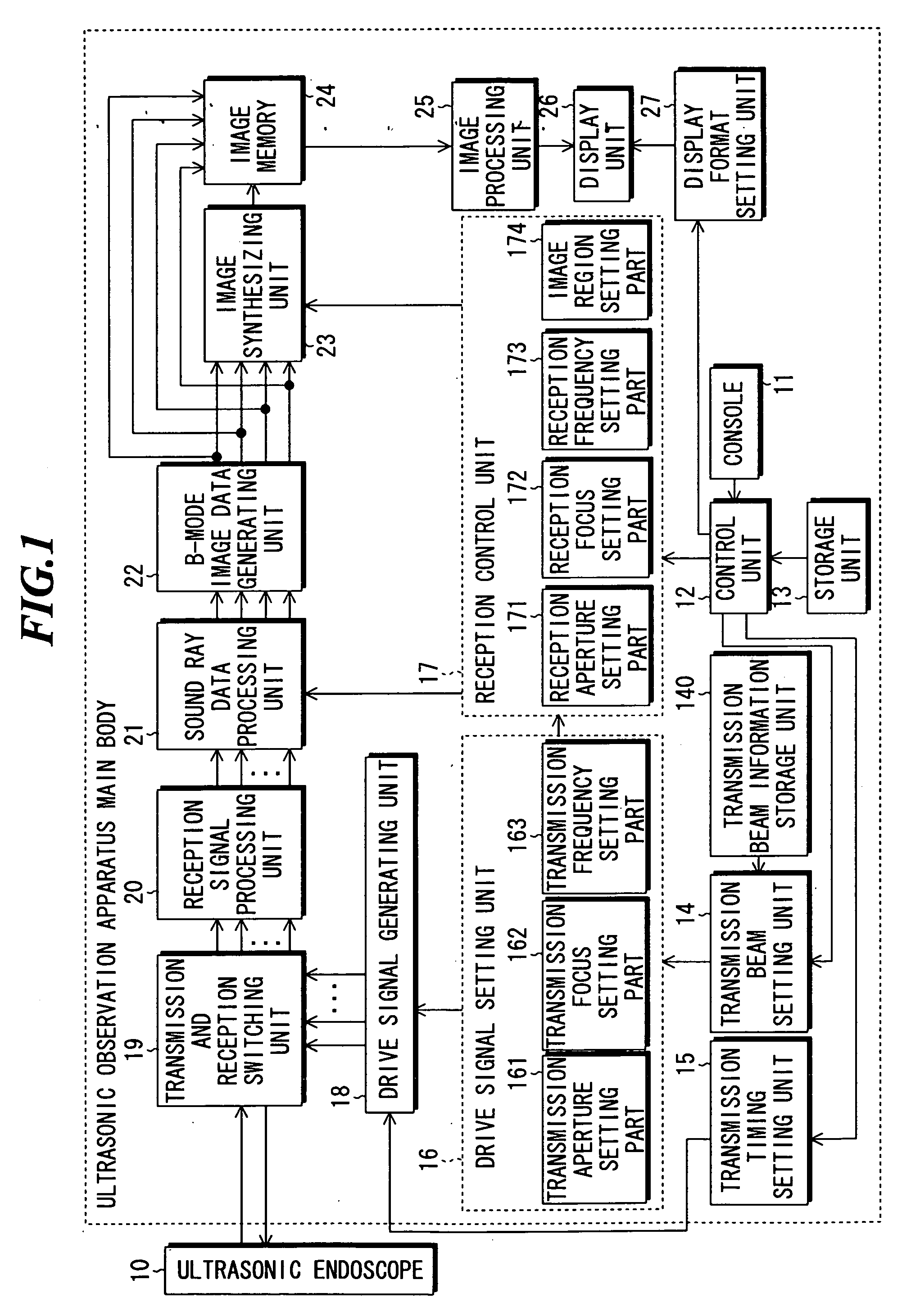
[0044]FIG. 1 is a block diagram showing a constitution of an ultrasonic observation apparatus according to the present invention.

[0045] As shown in FIG. 1, the ultrasonic observation apparatus according to the embodiment includes an electronic radial ultrasonic endoscope 10 and an ultrasonic observation apparatus main body to which the ultrasonic endoscope 10 can be connected.

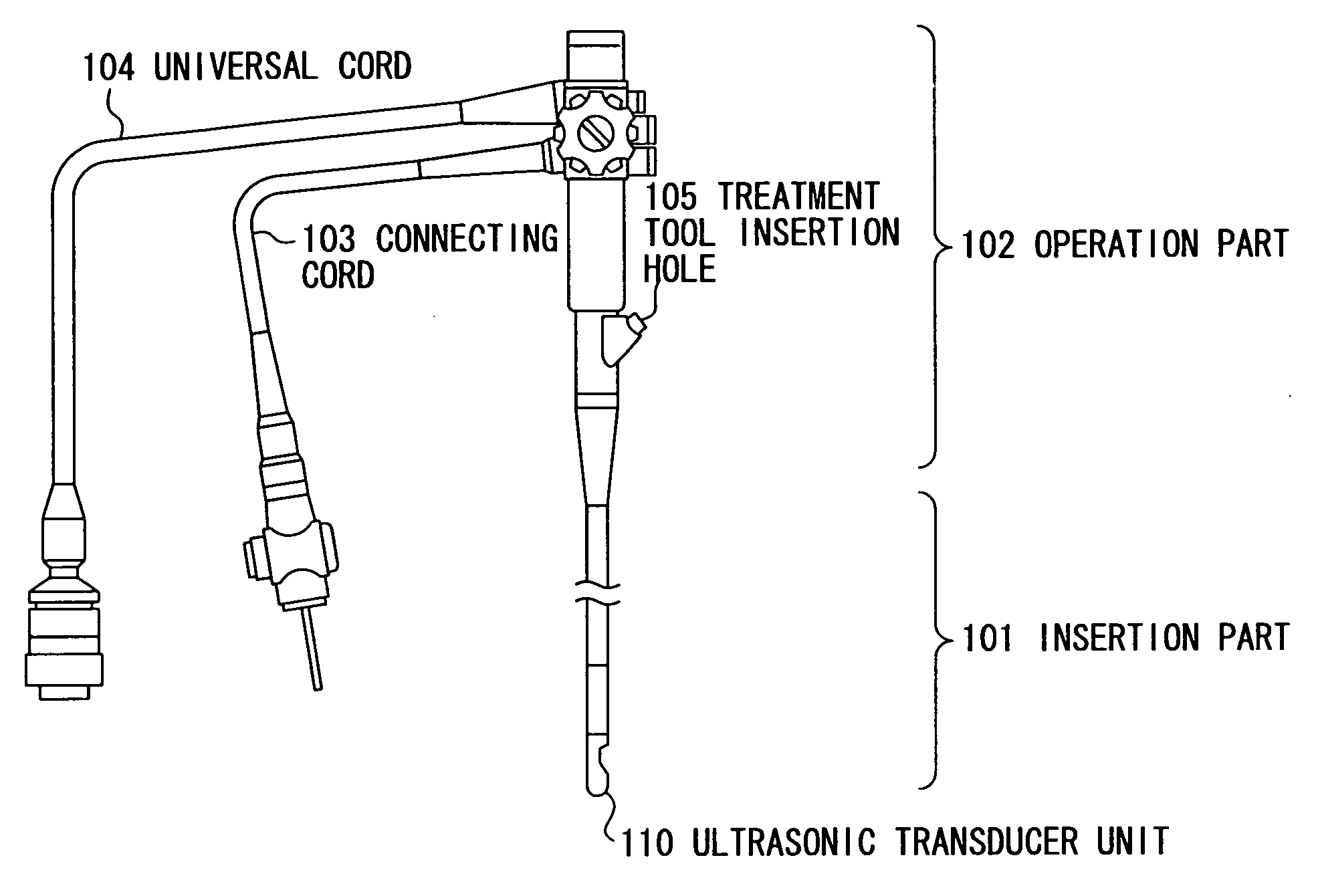
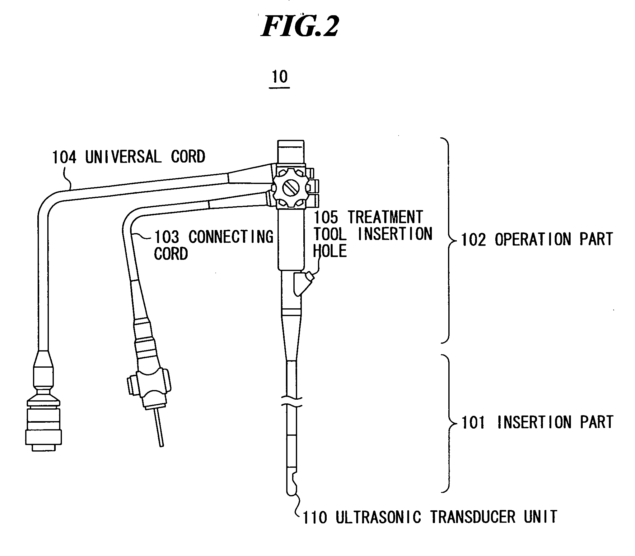
[0046]FIG. 2 is a schematic diagram showing a configuration of the ultrasonic endoscope 10 shown in FIG. 1. As shown in FIG. 2, the ultrasonic endoscope 10 includes an insertion part 101, an operation part 102, a connecting cord 103, and a universal cord 104.

[0047] The insertion part 101 of the ultrasonic endoscope 10 is an elongated flexible tube that can be inserted into a body of a patient. The operation part 102 is provided at the base end of the insertion part 101, connected to the ultrasonic observation apparatus main body via the connecting cord 103 and connected to a light source device via the univer...

second embodiment

[0113] An ultrasonic observation method according to the present invention will be explained by referring to FIGS. 11 to 13. In the embodiment, four ultrasonic beams having the same frequency but different focal depths from one another are substantially simultaneously transmitted.

[0114] In this case, the angular interval between adjacent ultrasonic beams is set to 90° (=360° / 4), and the transmission apertures, transmission focus, reception apertures, reception focus and image areas are set based on the following information stored in the transmission beam information storage unit 140 (FIG. 1).

[0115] Beam 1 (TB5): frequency of 4 MHz, aperture width of 6.4 mm, focal distance of 10 cm, image area equal to or more than 9 cm, beam diameter of 4.8 mm

[0116] Beam 2 (TB6): frequency of 4 MHz, aperture width of 6.4 mm, focal distance of 8 cm, image area equal to or more than 7 cm and less than 9 cm, beam diameter of 1.7 mm

[0117] Beam 3 (TB7): frequency of 4 MHz, aperture width of 6.4 mm, f...

third embodiment

[0124] Next, an ultrasonic observation method according to the present invention will be explained by referring to FIG. 13. In the embodiment, in the case where four ultrasonic beams having the same frequency but different focal depths from one another are substantially simultaneously transmitted, the ultrasonic beams are designed such that the beam diameters become the same at the focal positions.

[0125] In the second embodiment of the present invention, when the plural ultrasonic beams are formed, the focal distances are changed only by transmission focus setting without changing the aperture widths. Accordingly, the beam diameter at the focal position is smaller as the focal distance is shorter, and the beam diameter at the focal position is larger as the focal distance is longer (near the periphery in FIG. 12). Therefore, in the synthesized image shown in FIG. 12, the resolving power near the center is high, and gradually becomes lower toward the outer side. Contrary, in the embo...


PUM


Abstract

An ultrasonic observation apparatus in which the frame rate can be made higher than that in a mechanical or conventional electronic scan method. The ultrasonic observation apparatus includes: an ultrasonic endoscope including ultrasonic transducers; a transmission aperture setting unit for setting ultrasonic transducer groups as transmission apertures; a transmission frequency setting unit for setting respective frequencies of drive signal groups for the transmission apertures; a drive signal generating unit for generating the drive signal groups having the set frequencies; a reception aperture setting unit for setting ultrasonic transducer groups as reception apertures; a signal processing unit for performing signal processing on reception signal groups respectively outputted from the ultrasonic transducer groups; and a control unit for controlling the transmission aperture setting unit to sequentially change regions of the ultrasonic transducer groups to be set as the transmission apertures at a predetermined time interval.

Description

BACKGROUND OF THE INVENTION [0001] 1. Field of the Invention [0002] The present invention relates to an ultrasonic observation apparatus having an ultrasonic endoscope capable of being inserted into a body of a patient and taking ultrasonic tomographic images for medical diagnoses. [0003] 2. Description of a Related Art [0004] Recent years, an ultrasonic endoscope to be used by being inserted into a body cavity of a patient has been developed for medical diagnoses based on ultrasonic tomographic images around the body cavity of the patient. In an ultrasonic endoscope, a mechanical radial scan method has been generally adopted which performs the scan with viewing angle of 360° by mechanically rotating an array including plural ultrasonic transducers (ultrasonic vibrators) for transmitting and receiving ultrasonic waves. [0005] Further, an electronic radial scan method has been proposed which performs the scan with viewing angle of 360° by electronic scan. For example, Takeda et al., ...

Claims


Application Information

Patent Timeline
Patent Type & Authority Applications(United States)
IPC IPC(8): A61B8/14
CPCA61B8/12A61B8/4483G01S15/8979A61B8/488G01S7/5209A61B8/4488
Inventor KARASAWA, HIROYUKI
Owner FUJIFILM HLDG CORP
Why Eureka
Try Eureka