Emission Control System For An Engine

a technology of emission control system and engine, which is applied in the direction of machines/engines, mechanical equipment, separation processes, etc., can solve the problems of reducing the efficiency of the powertrain, the cost of the powertrain, and the use of separate air injection equipment, so as to reduce the hydrocarbon emissions of the engin

Inactive Publication Date: 2006-11-02
FORD GLOBAL TECH LLC
View PDF10 Cites 24 Cited by
  • Summary
  • Abstract
  • Description
  • Claims
  • Application Information

AI Technical Summary

Benefits of technology

[0002] It is well known to provide an internal combustion engine with an emission control system having a catalyst to reduce hydrocarbon emissions from the engine during running of the engine.

Problems solved by technology

However, it is a problem with a conventional emission control system that hydrocarbon emission are produced as soon as the engine starts but a conventional catalyst is unable to convert these emissions until it has reached a predetermined temperature normally referred to as its light-off temperature.
One disadvantage of the system proposed in U.S. Pat. No. 5,937,637 is that a separate air injection apparatus is used which adds not only to the cost of the powertrain but also to its complexity and the difficulty of accommodating the powertrain within the confines of a small engine bay.
It is a problem with such an arrangement that the exhaust gasses impinge directly against the hydrocarbon absorbing material and so it is difficult to maintain the absorbing material at a uniform temperature below that required for absorbtion with no desorbtion.

Method used


Image

  • Emission Control System For An Engine
  • Emission Control System For An Engine
  • Emission Control System For An Engine

Examples


Embodiment Construction

)

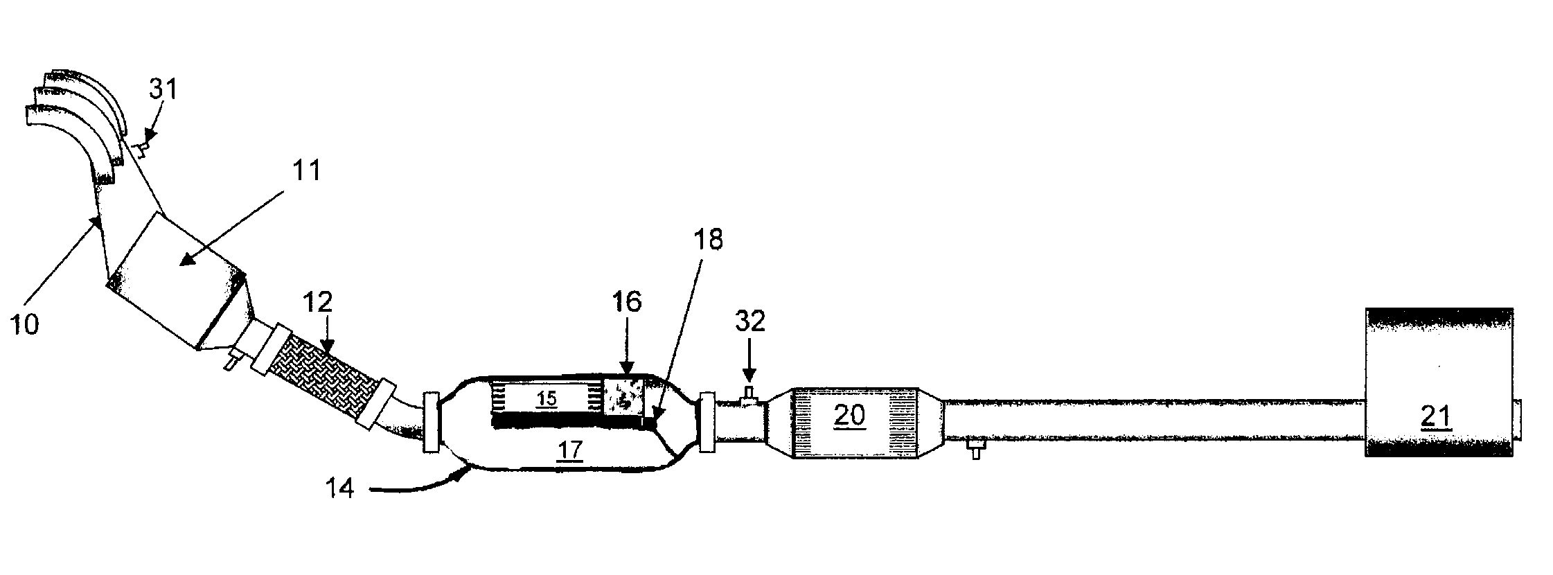
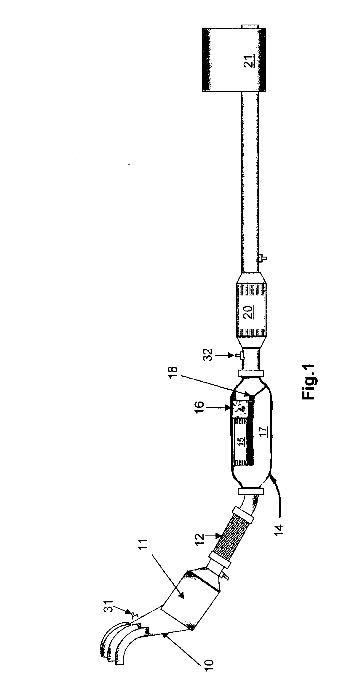
[0040] With particular reference to FIG. 1 there is shown an emission control system for a lean burn internal combustion engine (not shown). It will however be appreciated that the invention is equally applicable to non-lean burn engines and diesel engines.

[0041] The emission control system comprises of a three way catalyst 11 which is coupled to an exhaust manifold 10 of the engine, a combined exhaust gas cooler and hydrocarbon trap unit 14 and a lean NOx trap 20. Such a three way catalyst is often referred to as a close coupled catalyst due to its location close to the exhaust outlets from the engine.

[0042] The three way catalyst 11 is coupled via a flexible tube 12 to the combined exhaust gas cooler and hydrocarbon trap unit 14. The combined exhaust gas cooler and hydrocarbon trap unit 14 has an outlet which is coupled to the downstream mounted lean NOx trap 20. Exhaust gasses from the lean NOx trap 20 flow to a silencer unit 21 and then out to atmosphere via a tailpipe (not s...


PUM

PropertyMeasurementUnit
storage temperatureaaaaaaaaaa
light-off temperatureaaaaaaaaaa
temperatureaaaaaaaaaa

Abstract

An emission control system for an engine is disclosed in which an exhaust gas cooler is positioned upstream from a hydrocarbon trap in order to prevent premature desorbtion of hydrocarbons from the hydrocarbon trap. A bypass passage is also provided to allow the exhaust gas cooler to be bypassed to speed up the activation of a lean NOx trap positioned downstream from the hydrocarbon trap prior to hydrocarbon release.

Description

FIELD OF THE INVENTION [0001] This invention relates to internal combustion engines and in particular to an emission control system for an internal combustion engine providing reduced hydrocarbon emissions during engine warm up. BACKGROUND AND SUMMARY OF THE INVENTION [0002] It is well known to provide an internal combustion engine with an emission control system having a catalyst to reduce hydrocarbon emissions from the engine during running of the engine. [0003] However, it is a problem with a conventional emission control system that hydrocarbon emission are produced as soon as the engine starts but a conventional catalyst is unable to convert these emissions until it has reached a predetermined temperature normally referred to as its light-off temperature. There is therefore a period of time after start-up from cold during which hydrocarbon emissions are very high until the catalyst becomes active. [0004] It has therefore been proposed in, for example U.S. Pat. No. 5,937,637, to...

Claims


Application Information

Patent Timeline
Patent Type & Authority Applications(United States)
IPC IPC(8): F02M25/06F01N3/00B01D53/94F01N3/02F01N3/08F01N3/20
CPCB01D53/9422Y02T10/24B01D53/9486B01D53/9495B01D2255/91B01D2255/912F01N3/02F01N3/0205F01N3/0814F01N3/0835F01N3/0842F01N3/0871F01N3/2006F01N3/2046F01N3/2053Y02T10/26Y02T10/22B01D53/945Y02T10/12B01D53/94F01N3/08
Inventor KAY, DUNCANPEIRCE, GARYDAVIES, MARCUSCAINE, JON
Owner FORD GLOBAL TECH LLC
Why Eureka
Try Eureka