
Method for cleaning lithographic apparatus

Inactive Publication Date: 2006-11-02
INFINEON TECH AG
View PDF15 Cites 5 Cited by
  • Summary
  • Abstract
  • Description
  • Claims
  • Application Information

AI Technical Summary

Benefits of technology

[0012] The present invention includes a simple and fast method for cleaning photo-masks for UV-lithography.
[0014] When photo-masks are used in a clean room for some time, these photo-masks develop crystal contaminants, which grow with every use of the photo-mask. Especially by 193 nm lithography, crystal growth is relatively high. Surprisingly, such crystals disappear after a certain period of time if the photo-mask is placed into a vacuum chamber evacuated to a pressure of less than 100 mbar. Not only is better cleaning achieved, by the use of the vacuum alone than by the use of chemical etching solutions, but also the tendency of crystal growth is reduced in the further use of the photo-mask.
[0022] In an alternative embodiment, a lower frame that is glued to the mask and an upper frame which is fixed to the membrane are employed. These frames are then connected through screws and a gasket or by similar sorts of seals, for example, bayonet connectors. The advantage of this approach would be that the upper part from the pellicle can be removed from the mask without generating glue residue which would make a cleaning necessary. The mask with the affixed frame can then be cleaned with an electron shower or a water rinse, for example. Afterwards a new membrane can be fitted easily to the lower frame. Potentially it would even be possible to reuse the upper frame part with the membrane.
[0024] A disadvantage of this process is that the rest of the glue holding the pellicle on the photo-mask has to be removed so that the relatively strong chemicals and wet etching process can be applied. According to the present invention, the pellicle does not have to be removed, since the pellicle either comprises a hole from which the contaminants present on the photo-mask can escape or there is a valve provided so that the pressure between the pellicle and the photo-mask can be regulated. According to this aspect of the present invention, the removal of the pellicle before the cleaning of the photo-mask is not necessary any more and the photo-mask can be cleaned in a very simple and efficient manner. However, if desired, the pellicle can still be removed.

Problems solved by technology

When photo-masks are used in a clean room for some time, these photo-masks develop crystal contaminants, which grow with every use of the photo-mask.

Method used


Image

  • Method for cleaning lithographic apparatus
  • Method for cleaning lithographic apparatus
  • Method for cleaning lithographic apparatus

Examples


Embodiment Construction

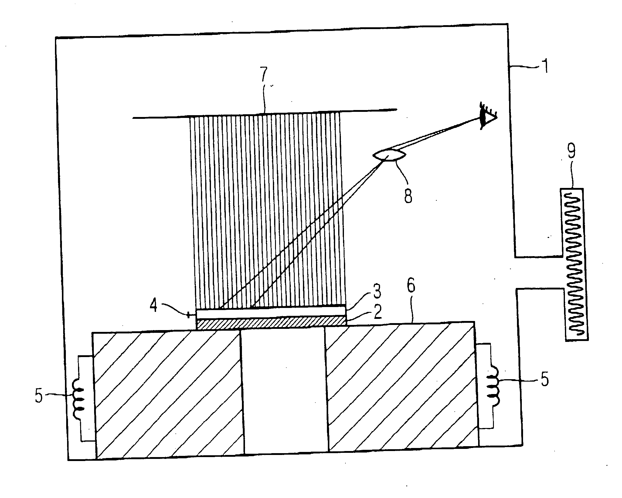
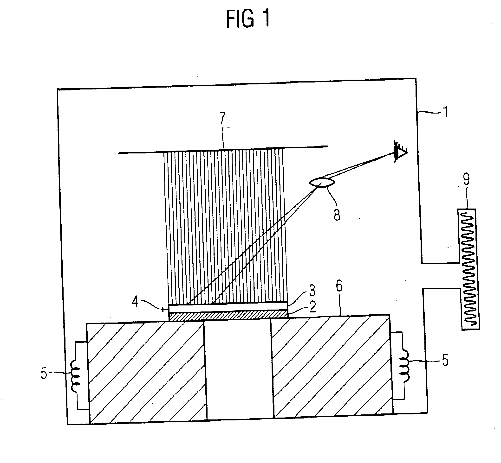
[0034]FIG. 1 schematically depicts a chamber 1 for cleaning a photo-mask 2, wherein the photo-mask is positioned in the chamber by providing a surface 6 on which a photo-mask is placed. The photo-mask 2 also includes a pellicle 3 mounted on the photo-mask, wherein a valve or venthole 4 is provided between the pellicle and photo-mask, to regulate the pressure in the space between the photo-mask and the pellicle. The surface 6 on which the photo-mask has been placed is provided with a heater 5 which controls the temperature of the photo-mask 2.

[0035] After placing the photo-mask 2 in the chamber 1, the chamber is evacuated for example, by a vacuum pump 9 to a pressure of approximately less than 100 mbar. In the chamber, an electron shower 7 is generated, and the surface of the photo-mask 8 is inspected. After inspecting the surface in regular intervals, the photo-mask no longer has crystal growth present. After no more crystals are detected on the surface of the photo-mask, the chamb...


PUM


Abstract

A method is provided for cleaning a photo-mask by placing the photo-mask in an evacuated chamber for a certain period of time.

Description

FIELD OF THE INVENTION [0001] The present invention relates to a method for cleaning a lithographic apparatus. BACKGROUND [0002] The term “lithographic apparatus” as used hereinafter should be broadly interpreted as referring to a device that is used in a method for patterning semiconductor substrates. An example of such a lithographic device is a mask, also called a photo-mask or “reticle”. The concept of a mask is well known in lithography, and it includes mask types such as binary, alternating phase-shift and attenuated phase-shift, as well as various hybrid mask types. The present invention especially relates to masks used in UV lithography, and especially with a wavelength of less than 250 nm. [0003] In the manufacturing of semiconductor integrated circuits, a layout design is usually transferred to a mask comprising a glass or quartz substrate and a metal layer deposited thereon. This transfer of the layout is a common step in the manufacturing of semiconductors and is well kn...

Claims


Application Information

Patent Timeline
IPC IPC(8): B08B3/12B08B7/04B08B7/00
CPCG03F1/82B08B7/0035
Inventor KLINGBEIL, PATRICKPITSCHKE, JOERGBONNESS, ANJA
Owner INFINEON TECH AG
Learn More