Floating wetland structures for use in water remediation

a technology for wetlands and water remediation, applied in water cleaning, sustainable biological treatment, biological water/sewage treatment, etc., can solve the problem that the floating panels remain quite buoyant, and achieve the effect of increasing vegetation, avoiding inundation, and increasing the elimination of nitrogen oxides

Inactive Publication Date: 2006-11-02
3R FOAM
View PDF8 Cites 38 Cited by
  • Summary
  • Abstract
  • Description
  • Claims
  • Application Information

AI Technical Summary

Benefits of technology

[0009] The present invention provides floating wetland structures that enable the growth of surface vegetation upon the surface area of relatively deep lagoons or reservoirs that would otherwise be unable to support surface vegetation. By providing a floating surface that is compatible with wetland vegetation, the floating structures of the invention increase the amount of vegetation within the wetland system and thereby increase the elimination of nitrogen oxides from the water and soil of the system. The wetland structures are porous such that surface vegetation may root through the structures without disturbing the structural integrity of the structures. As a further result of being porous, the structures allow rainwater to readily pass through, thereby avoiding inundation during storms and the like. The structures are capable of holding soil, peat moss, or other growth medium upon their surface, and simultaneously prevent such growth medium or other debris from entering the underlying water. The wetland structures of the invention are further durable, economical and easily installed.

Problems solved by technology

Although relatively dense, the floatation panels remain quite buoyant.

Method used


Image

  • Floating wetland structures for use in water remediation
  • Floating wetland structures for use in water remediation
  • Floating wetland structures for use in water remediation

Examples


Embodiment Construction

[0021] The present invention now will now be described more fully hereinafter with reference to the accompanying drawings, in which advantageous embodiments of the invention are shown. This invention may, however, be embodied in many different forms and should not be construed as limited to the embodiments set forth herein; rather, these embodiments are provided so that this disclosure will be thorough and complete, and will fully convey the scope of the invention to those skilled in the art. Like numbers refer to like elements throughout.

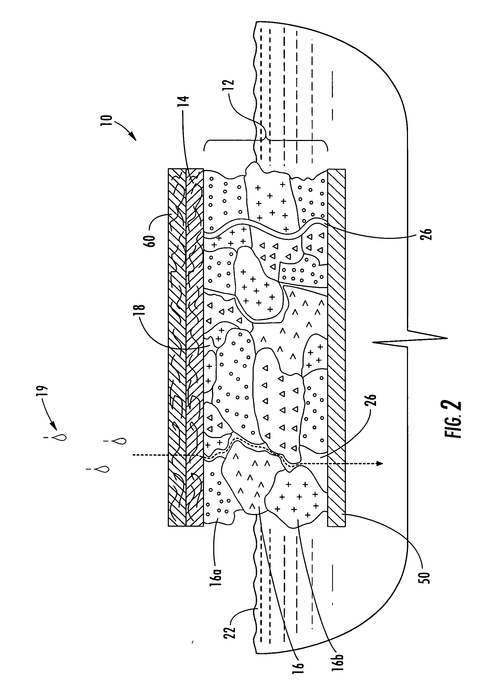
[0022]FIG. 2 provides a grossly enlarged cross sectional view of a section of an exemplary structure 10 suitable for use in the present invention. In general, the floatation panel 12 portion of the structure 10 is formed from foam particles 16 of various sizes, shapes and densities that have been bonded together to provide a cohesive structure. Further, the foam particles 16 forming the floatation panel 12 are typically randomly arranged into a pi...


PUM

PropertyMeasurementUnit
widthaaaaaaaaaa
diameteraaaaaaaaaa
thicknessaaaaaaaaaa

Abstract

Floating wetland structures of the invention are generally formed from one or more floatation panels made of a plurality of polymeric foam particles arranged in a piled laminate structure. The foam particles are arranged within the piled laminate structure so as to define void pathways between at least a portion of said foam particles. The void pathways within the piled laminate structure are of sufficient size and quantity to allow rainwater to flow through and of such an orientation to allow for the roots of vegetation to easily penetrate the structure.

Description

FEDERALLY SPONSORED RESEARCH OR DEVELOPMENT [0001] The research underlying this invention may have been supported in part with funds from the United States Department of Agriculture, under Cooperative Research and Development Agreement (CRADA) No. 58-3K95-M-1021. The United States Government may have an interest in the subject matter of this invention.FIELD OF THE INVENTION [0002] The present invention relates to floating wetlands structures. More particularly, the invention relates to structures that are capable of floating atop bodies of water and capable of providing a basis for vegetative growth. BACKGROUND OF THE INVENTION [0003] Evolving environmental regulations and sensitivities provide a constant impetus to provide improved waste management systems and techniques. In particular, there is a call for improved methods of treating ground water, open bodies of water, and wetlands. Presently, agricultural practices account for the largest single contribution to non-point source p...

Claims


Application Information

Patent Timeline
Patent Type & Authority Applications(United States)
IPC IPC(8): C02F3/32
CPCC02F3/327Y10S210/906Y10S210/903Y02W10/10Y02W10/37
Inventor SVIRKLYS, FREDSHANKLIN, DENNIS
Owner 3R FOAM
Why Eureka
Try Eureka