
Vibration damper

a vibration damper and damper technology, applied in the direction of spring/damper design characteristics, machine supports, machine frames, etc., can solve the problems of generating noise on horizontal surfaces such as floors, requiring structures and/or equipment to be isolated, and common unwanted noise and vibration in many environments, etc., to achieve effective absorption of noise and vibration, easy installation and use, and low manufacturing cost

Inactive Publication Date: 2006-11-02
DOWNEY PAUL C
View PDF13 Cites 31 Cited by
  • Summary
  • Abstract
  • Description
  • Claims
  • Application Information

AI Technical Summary

Benefits of technology

[0014] The vibration damper effectively absorbs noise and vibration, is inexpensive to manufacture and is easy to install and use. When used beneath vibrating equipment, the vibration damper virtually eliminates noise and vibration from propagating to surrounding structures. When used beneath sensitive measurement and high-tolerance equipment, the vibration damper effectively inhibits vibration generated in the surrounding environment from propagating to the equipment supported by the vibration damper.

Problems solved by technology

Unwanted noise and vibration is common in many environments.
Although such noise and vibration can be tolerated in some cases, in many situations it cannot thus requiring structures and / or equipment to be isolated from the sources of noise and vibration.
For example, in many circumstances, noise is generated on horizontal surfaces such as floors due to various impacts.
This noise often propagates into surrounding structures creating undesirable noise and vibration pollution.
In commercial environments, large commercial and industrial machinery and equipment, which vibrates during use, often results in impact and / or vibrational noise passing through the floor and into adjacent structures.
In residential environments, exercise equipment such as treadmills, Jacuzzi tubs, whirlpool baths and hot tubs, which vibrate during use, result in impact and / or vibrational noise passing into adjacent structures.
Unfortunately, to-date these solutions to deal with unwanted noise and vibration have proven either to be inadequate, too expensive and / or too complicated.

Method used


Image

  • Vibration damper
  • Vibration damper
  • Vibration damper

Examples


Embodiment Construction

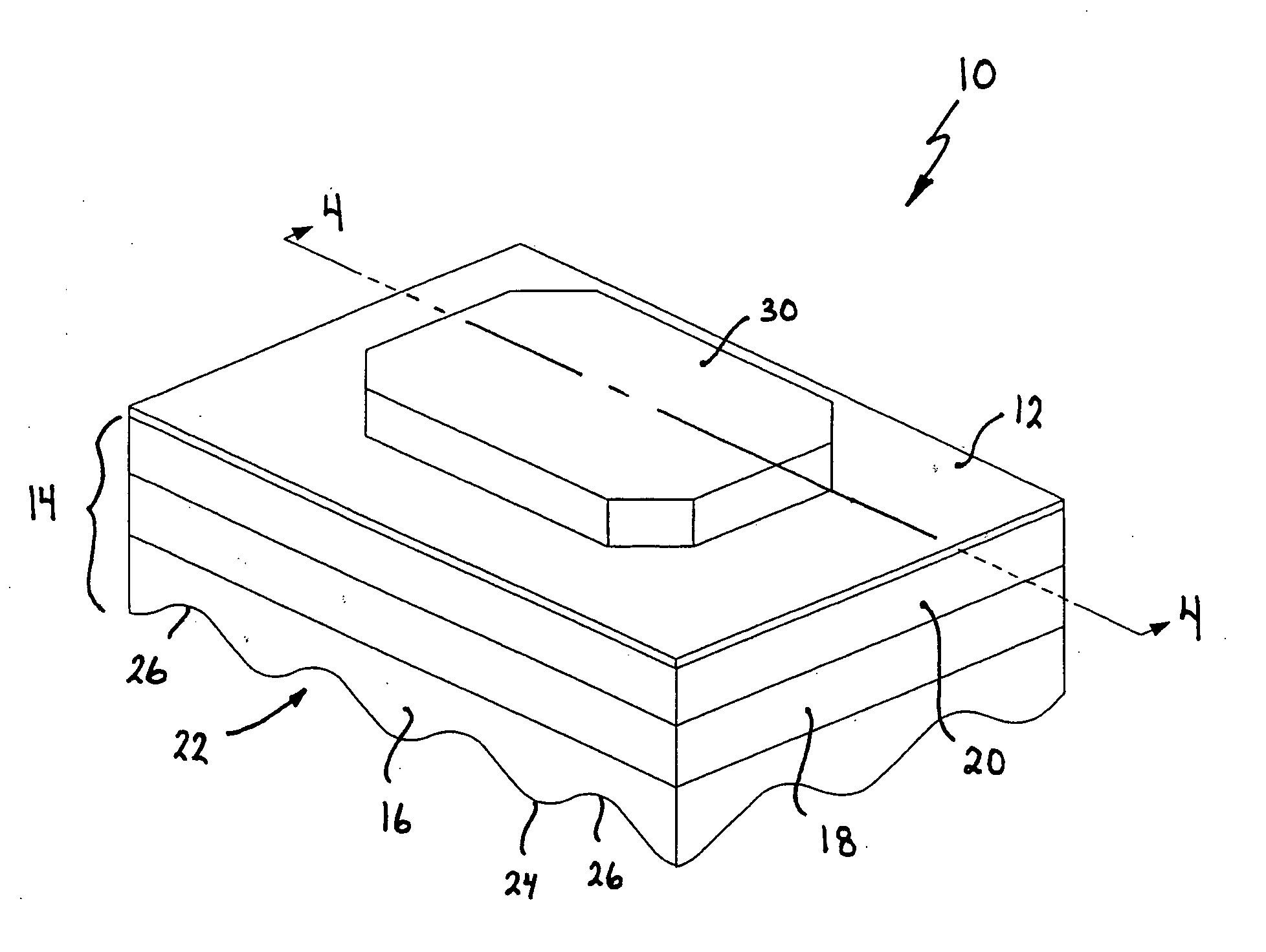
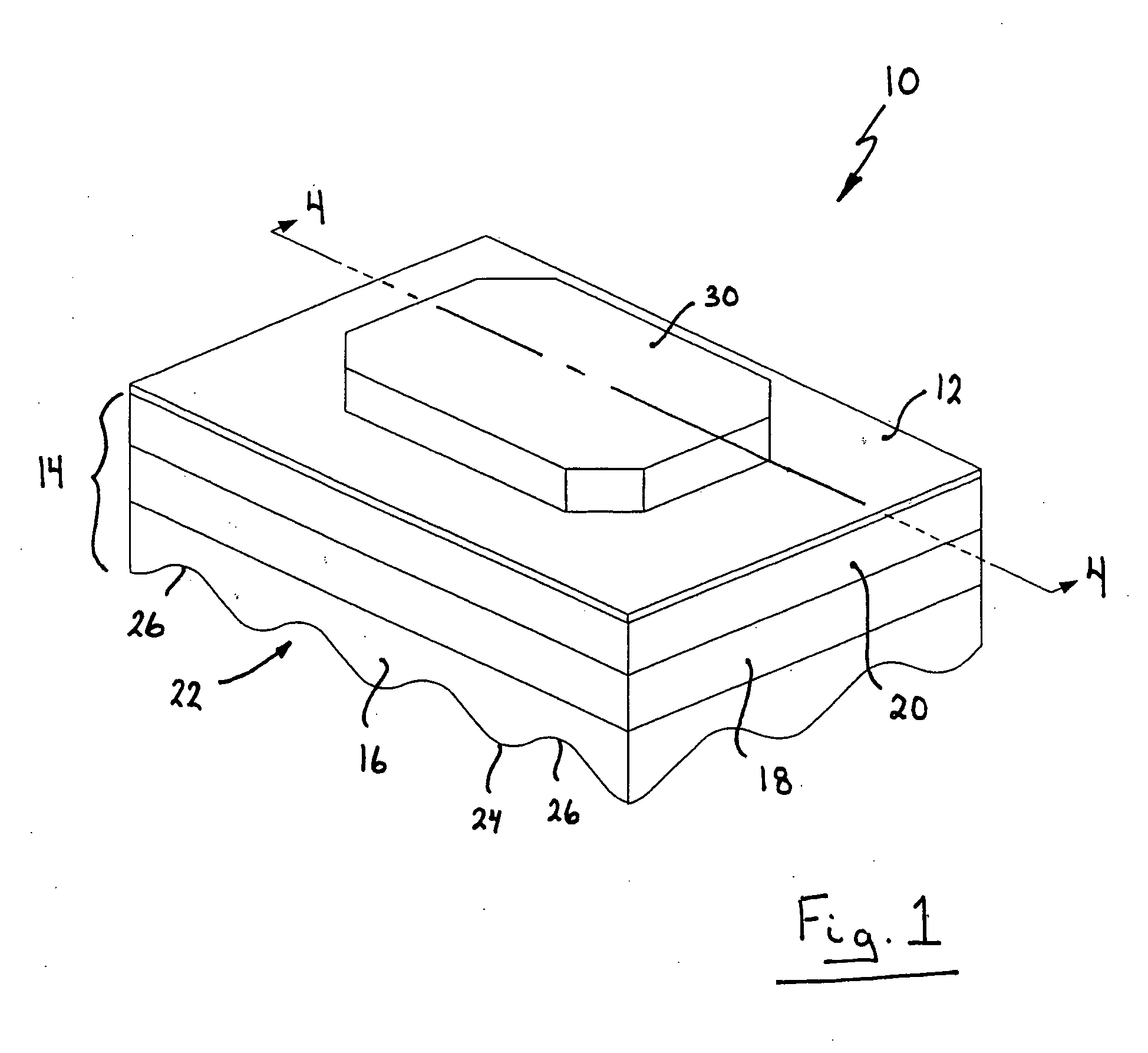
[0020] Turning now to FIGS. 1 to 4, a vibration damper is shown and is generally identified by reference numeral 10. Vibration damper 10 is designed to act between a support surface such as an underlying floor surface and residential or commercial equipment. Depending on the nature of the equipment to be supported, vibration damper 10 acts to inhibit impact and vibrational noise generated by the equipment from propogating to surrounding structures and / or to inhibit vibration in the surrounding environment from propogating to the equipment.

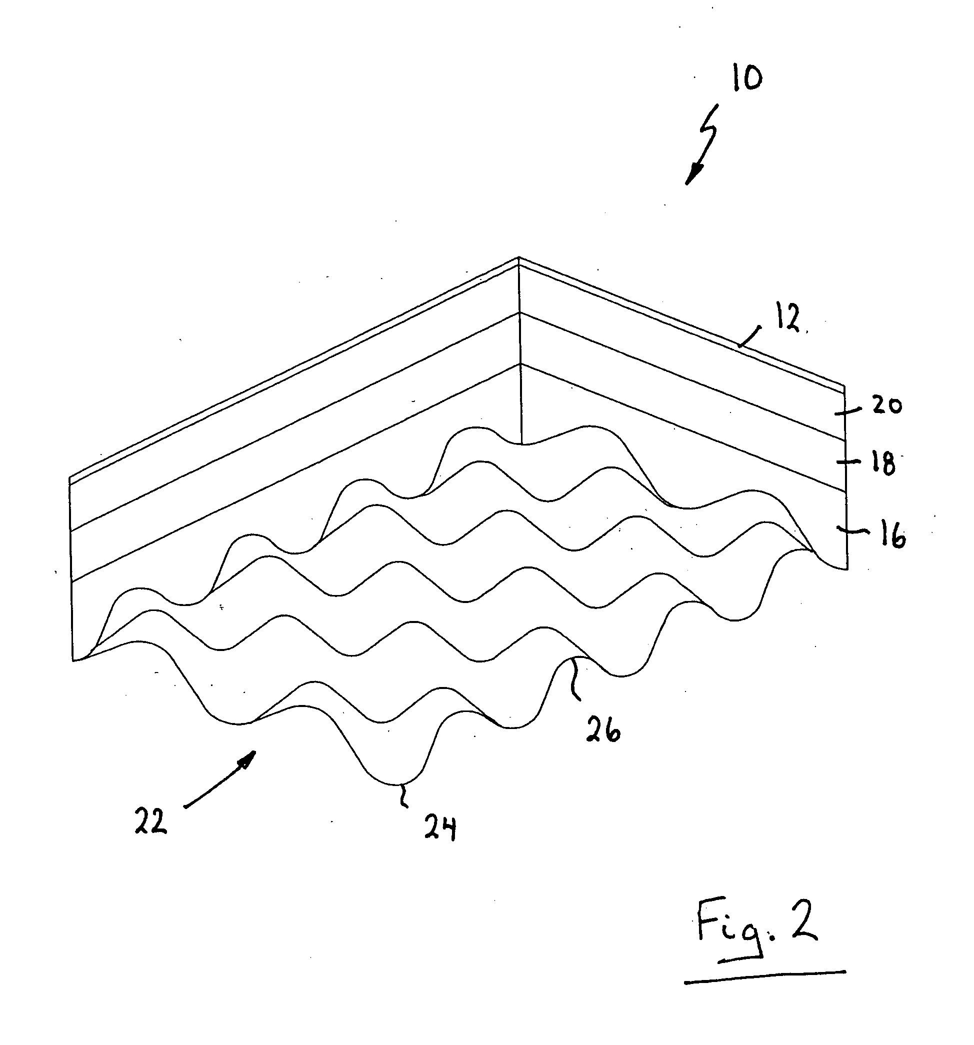
[0021] As can be seen, vibration damper 10 includes a load bearing plate 12 disposed on a vibration dampening structure 14. The vibration dampening structure 14 in this example includes a slip resistant lower layer 16 and a pair of intermediate foam layers 18 and 20 disposed between the lower layer 16 and the load bearing plate 12.

[0022] The bottom surface 22 of the lower layer 16 is contoured to define peaks 24 and valleys 26 that are sequential...


PUM


Abstract

A vibration damper comprises a vibration dampening structure and a load bearing plate disposed on the vibration dampening structure. The vibration dampening structure includes a slip resistant layer and at least one foam layer disposed between the slip resistant layer and the load bearing plate. A resilient mounting layer is disposed on the load bearing plate. The vibration damper may act directly between an underlying support surface and equipment or may act between the underlying support surface and a sheet of flooring.

Description

FIELD OF THE INVENTION [0001] The present invention relates generally to noise and vibration absorption and more particularly, to vibration damper for mitigating noise and vibration. BACKGROUND OF THE INVENTION [0002] Unwanted noise and vibration is common in many environments. Although such noise and vibration can be tolerated in some cases, in many situations it cannot thus requiring structures and / or equipment to be isolated from the sources of noise and vibration. For example, in many circumstances, noise is generated on horizontal surfaces such as floors due to various impacts. This noise often propagates into surrounding structures creating undesirable noise and vibration pollution. In commercial environments, large commercial and industrial machinery and equipment, which vibrates during use, often results in impact and / or vibrational noise passing through the floor and into adjacent structures. In residential environments, exercise equipment such as treadmills, Jacuzzi tubs, ...

Claims


Application Information

Patent Timeline
IPC IPC(8): F16M7/00
CPCF16F1/37F16F2230/02F16F1/44
Inventor DOWNEY, PAUL C.
Owner DOWNEY PAUL C
Learn More