White light emitting device

a light-emitting device and white light technology, applied in the direction of discharge tube luminescnet screens, energy-saving lighting, sustainable buildings, etc., can solve the problems of low color rendering index (cri), obstructing the implementation of highly efficient, white leds, etc., and achieves high light-emitting efficiency and improved structure

Active Publication Date: 2006-11-02
SAMSUNG ELECTRONICS CO LTD
View PDF14 Cites 122 Cited by
  • Summary
  • Abstract
  • Description
  • Claims
  • Application Information

AI Technical Summary

Benefits of technology

[0007] To solve the above-described problems, the present disclosure provides a white li

Problems solved by technology

This method provides high emitting efficiency but leads to a low color rendering index (CRI).
However, such inorganic phosphors, especially red

Method used


Image

  • White light emitting device
  • White light emitting device
  • White light emitting device

Examples


second embodiment

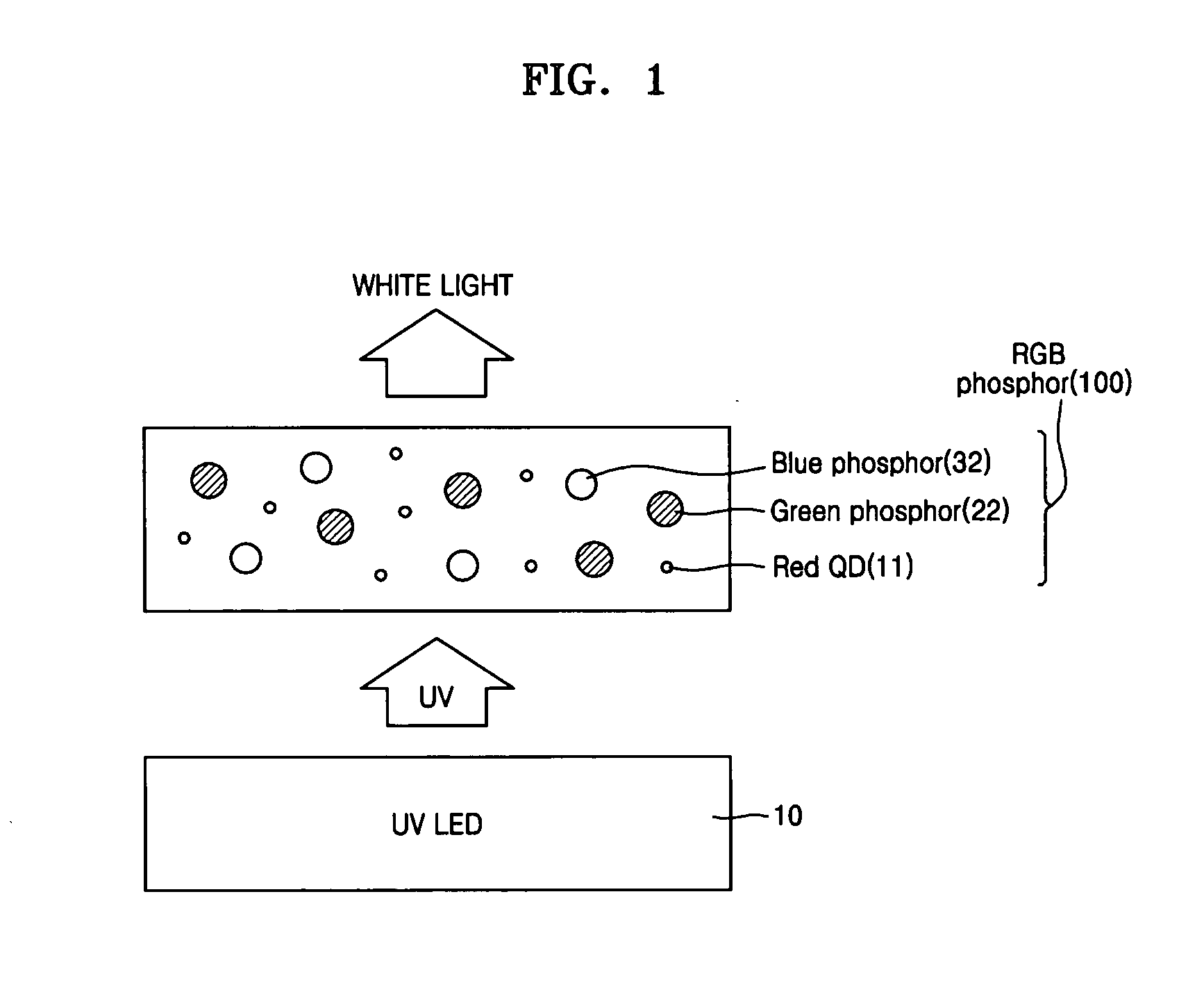
[0035]FIG. 2 is a schematic cross-sectional view of a white LED according to the present disclosure. Like reference numerals in the drawings denote like elements, and thus their description will be omitted.

[0036] In the second embodiment, a phosphor 110 has a multi-layered structure, and includes a first phosphor layer 14, a second phosphor layer 24, and a third phosphor layer 34 sequentially formed on the UV light emitting device 10. The first phosphor layer 14 includes at least one of red light emitting nanoparticles and red inorganic phosphors. The second phosphor layer 24 includes at least one of green light emitting nanoparticles and green inorganic phosphors. The third phosphor 34 includes at least one of blue light emitting nanoparticles and blue inorganic phosphors.

[0037] In particular, referring to FIG. 2, the first phosphor layer 14 includes red light emitting quantum dots 11, the second phosphor layer 24 includes a green inorganic phosphor 22, and the third phosphor laye...

third embodiment

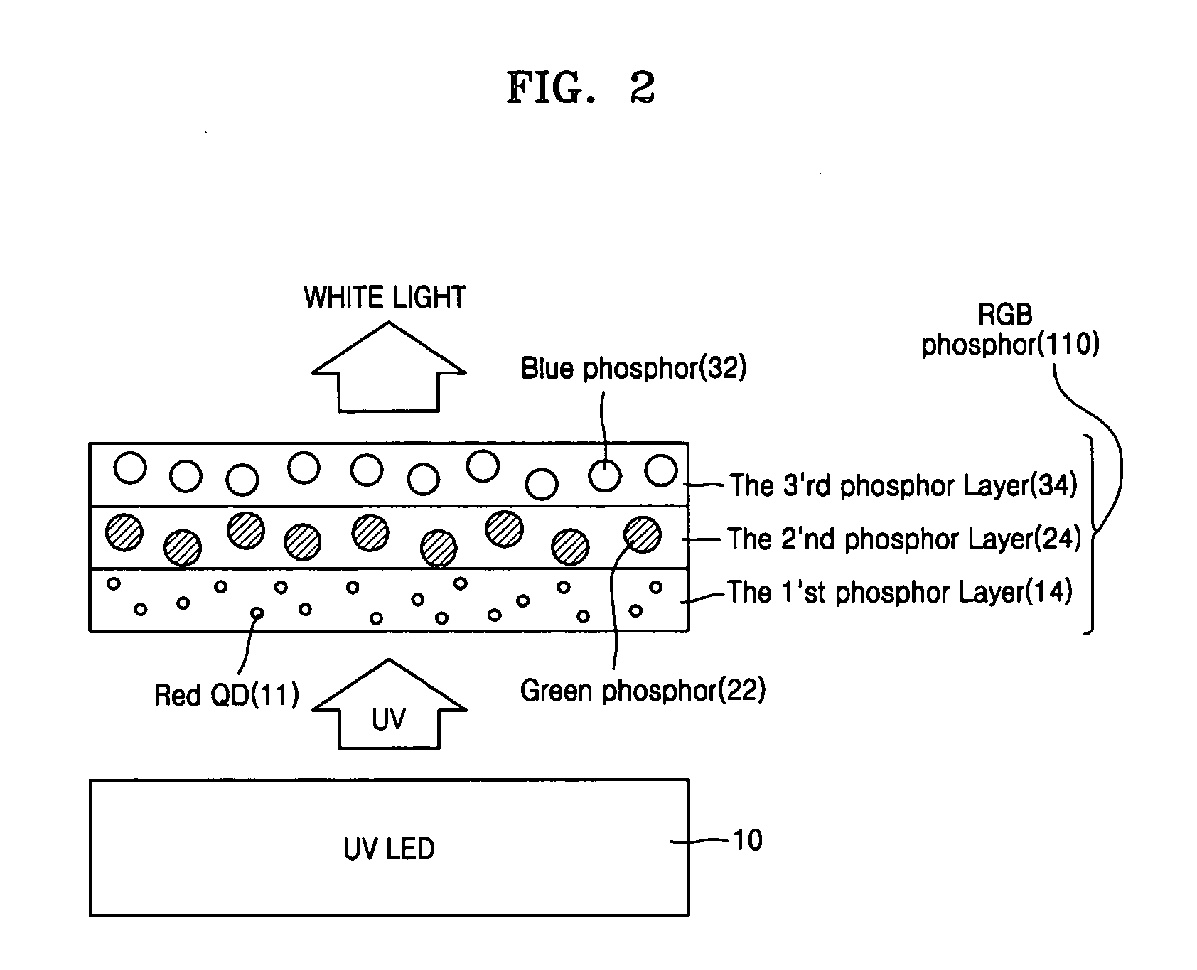
[0039]FIG. 3 is a schematic cross-sectional view of a white LED according to the present disclosure. Like reference numerals in the drawings denote like elements and thus their description will be omitted.

[0040] According to the third embodiment, a phosphor 120 has a multi-layered structure and includes a first phosphor layer 14 and a fourth phosphor layer 40, which are sequentially formed on the UV LED 10. The first phosphor layer 140 includes at least one of red light emitting nanoparticles and red inorganic phosphor, and the fourth phosphor layer 40 includes at least one of blue light emitting nanoparticles and blue inorganic phosphor. In particular, referring to FIG. 3, the first phosphor layer 14 includes red light emitting quantum dots 11, and the fourth phosphor layer 40 include a green inorganic phosphors 22 and a blue inorganic phosphor 32. As described above, using a phosphor including light emitting particles with high light emitting efficiency together with inorganic pho...


PUM


Abstract

A white LED with an improved structure for high light emitting efficiency is provided. The white LED includes a light source device and a phosphor containing light emitting nanoparticles and an inorganic phosphor which emit white light by being excited by the light source.

Description

CROSS-REFERENCE TO RELATED PATENT APPLICATION[0001] Priority is claimed to Korean Patent Application No. 10-2005-0036685, filed on May 2, 2005, in the Korean Intellectual Property Office, the disclosure of which is incorporated herein in its entirety by reference. BACKGROUND OF THE INVENTION [0002] 1. Field of the Disclosure [0003] The present disclosure relates to a white light emitting device (LED), and more particularly, to a white LED having an improved structure for higher light emission efficiency. [0004] 2. Description of the Related Art [0005] As the light emitting efficiency of nitride semiconductor based blue and green light emitting devices (LEDs) and red LEDs using InGaAIP has increased, attempts to use such LEDs as lighting device beyond the current wide use for displays are expanding worldwide. LED light sources have superior characteristics to conventional light sources, i.e., very small size, 10% less power consumption, 10 times longer life time, 1000 times faster re...

Claims


Application Information

Patent Timeline
IPC IPC(8): H01J1/62H01J63/04H01L33/06H01L33/32H01L33/50
CPCC09K11/025C09K11/565C09K11/7734C09K11/7739Y02B20/181H01L33/502H01L33/504H05B33/14C09K11/883Y02B20/00
Inventor KIM, BYUNG-KICHO, KYUNG-SANGJANG, EUN-JOO
Owner SAMSUNG ELECTRONICS CO LTD
Why Eureka
Try Eureka