Method and apparatus for performing optical imaging using frequency-domain interferometry

Active Publication Date: 2006-11-02
THE GENERAL HOSPITAL CORP
View PDF99 Cites 398 Cited by
  • Summary
  • Abstract
  • Description
  • Claims
  • Application Information

AI Technical Summary

Benefits of technology

[0017] Exemplary embodiments according to the present invention improves current data acquisition speeds and availability of sources compared with OCT. Shot noise is due to the statistical fluctuations of the current that are due to the quantized or discrete electric charges. The reduction of shot noise allows for much lower source powers or much higher acquisition rates. Limitations in current data acquisition rates (˜4 frames/sec) are imposed by available source power and availability of fast mechanisms for scanning delay. An increase in the sensitivity of the detection by a factor of 8 would allow real time imaging at a speed of about 30 frames per second. An increase of the sensitivity by a factor of about 1,000-2,000 allows for the use of sourc

Problems solved by technology

Multiple variants of the OCT techniques have been described, but many suffer from less than optimal signal to noise ratio (“SNR”), resulting in non-optimal resolution, low imaging frame rates, and poor depth of penetration.
Thus, boosting power is not feasible to increase SNR in such environments.
There are, however, a number of disadvantages associated with using a CCD device.
First, CCD devices are relatively expensive compared to a single-element photo-receiver.
Secondly, the previously described method uses a single CCD to acquire the data.
Since the cha

Method used


Image

  • Method and apparatus for performing optical imaging using frequency-domain interferometry
  • Method and apparatus for performing optical imaging using frequency-domain interferometry
  • Method and apparatus for performing optical imaging using frequency-domain interferometry

Examples


Example

[0055] Throughout the drawings, the same reference numerals and characters, unless otherwise stated, are used to denote like features, elements, components, or portions of the illustrated embodiments. Moreover, while the present invention will now be described in detail with reference to the Figures, it is done so in connection with the illustrative embodiments.

DETAILED DESCRIPTION

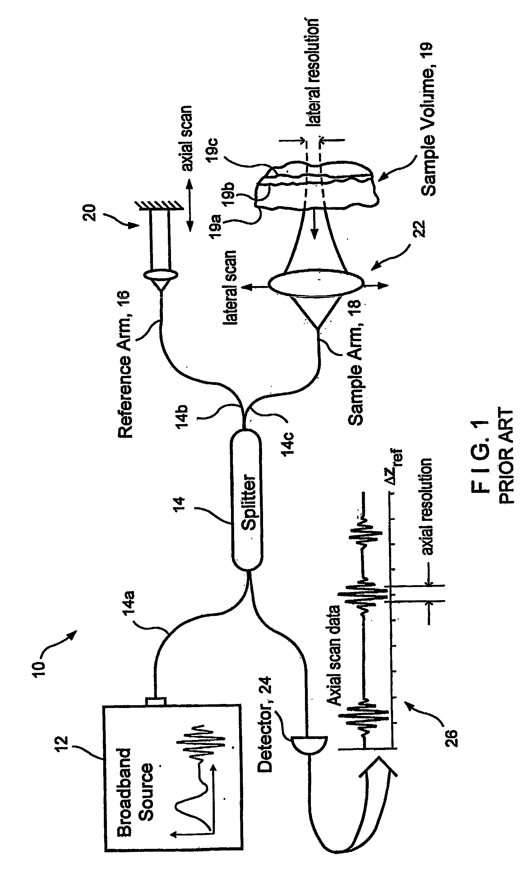
[0056]FIG. 1 shows an exemplary prior art time domain optical coherence tomography (“OCT”) system 10 which includes a broadband source 12 that provides a signal to a first arm 14a of two-by-two splitter 14. The splitter divides the signal provided thereto at port 14a, and provides a first portion of the signal at a port 14b coupled to a reference arm 16. The splitter 14 also provides a second portion of the signal at a port 14c coupled to a sample arm 18.

[0057] The sample arm 18 terminates at a sample volume 19 and an arrangement 22 for providing a lateral scan of the sample volume is disposed in the sa...


PUM


Abstract

An apparatus and method are provided. In particular, at least one first electro-magnetic radiation may be provided to a sample and at least one second electro-magnetic radiation can be provided to a non-reflective reference. A frequency of the first and/or second radiations varies over time. An interference is detected between at least one third radiation associated with the first radiation and at least one fourth radiation associated with the second radiation. Alternatively, the first electro-magnetic radiation and/or second electro-magnetic radiation have a spectrum which changes over time. The spectrum may contain multiple frequencies at a particular time. In addition, it is possible to detect the interference signal between the third radiation and the fourth radiation in a first polarization state. Further, it may be preferable to detect a further interference signal between the third and fourth radiations in a second polarization state which is different from the first polarization state. The first and/or second electro-magnetic radiations may have a spectrum whose mean frequency changes substantially continuously over time at a tuning speed that is greater than 100 Tera Hertz per millisecond.

Description

CROSS REFERENCE TO RELATED APPLICATION(S) [0001] This application claims priority from U.S. provisional application No. 60 / 514,769 filed on Oct. 23, 2003, the entire disclosure of which is incorporated herein by reference.FIELD OF THE INVENTION [0002] The present invention relates generally optical imaging, and more particularly to method and apparatus for performing optical imaging using frequency-domain interferometry. BACKGROUND OF THE INVENTION [0003] As is known in the art, optical interferometric reflectometry is a powerful tool for performing non-invasive, high-resolution (˜10 μm), cross-sectional imaging of a biological or other sample, to visualize micro-structural optical properties such as reflection, absorption, scattering, attenuation, birefringence, and spectroscopic analysis. There are a number of interferometric imaging techniques that are known in the art. These techniques in general can be divided into two major categories: (i) time-domain technique, and (ii) frequ...

Claims


Application Information

Patent Timeline
IPC IPC(8): G01B11/02A61B5/00G01J9/02G01N21/47G02B27/48
CPCA61B5/0059G01B9/02084A61B5/7257G01J3/02G01J3/0208G01J3/021G01J3/0218G01J3/0264G01J3/453G01J9/0215G01N21/4795G02B27/48H01S3/08009H01S3/08063H01S3/105H01S5/141H01S5/146G01B9/02004G01B9/02002G01B9/0209G01B9/02091G01B2290/70G01B9/02081G01B2290/45G01B9/02083G01B9/02043G01B9/02075A61B5/0066G02F1/093G02F1/11G01J9/02G01J9/00G01B9/02A61B5/00H01S5/0071H01S5/14H01S5/1025H01S3/1068H01S5/0078H01S5/5045G02B6/3604G02B26/12H01S3/0071H01S3/0078
Inventor YUN, SEOK-HYUNEUGENE, BRETTTEARNEY, GUILLERMO J.DE BOER, JOHANNES FITZGERALD
Owner THE GENERAL HOSPITAL CORP
Why Eureka
Try Eureka