Airplane strength and strain detection method and airplane strength and strain detecting system adopting same

A technology for aircraft strength and detection systems, applied in signal transmission systems, non-electrical signal transmission systems, electric/magnetic solid deformation measurement, etc., can solve the problems of difficult elimination of sensor signal errors, complex detection circuit wiring, and low signal acquisition efficiency , to achieve the effect of omitting the resistance compensation circuit, improving layout efficiency and reducing wiring complexity

Inactive Publication Date: 2013-01-16
8TH RES INST OF CETC
View PDF3 Cites 7 Cited by
  • Summary
  • Abstract
  • Description
  • Claims
  • Application Information

AI Technical Summary

Problems solved by technology

[0006] The purpose of the present invention is to provide a method for aircraft strength and strain detection, which solves the technical problems of difficult elimination of sensor signal errors, low signal acquisition efficiency, and complicated acquisition lines in traditional strength and strain detection.
[0007] Another object of the present invention is to provide an aircraft strength and strain detection system formed by the above method of aircraft strength and strain detection, which solves the technical problems of complex detection circuit wiring and low signal processing capability in traditional strength and strain detection

Method used


Image

  • Airplane strength and strain detection method and airplane strength and strain detecting system adopting same
  • Airplane strength and strain detection method and airplane strength and strain detecting system adopting same
  • Airplane strength and strain detection method and airplane strength and strain detecting system adopting same

Examples


Embodiment Construction

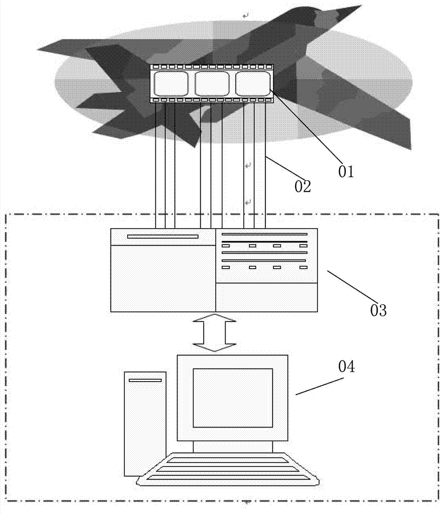
[0040] Aircraft strength strain detection method of the present invention mainly passes through the following steps:

[0041] Step 1: Install an on-board signal processing module on the aircraft, install a monitoring display module in the monitoring room, and use an optical cable to establish a data transmission channel between the two;

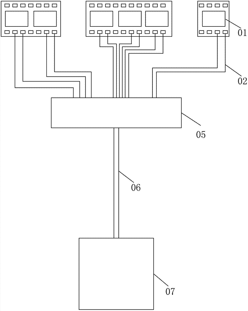
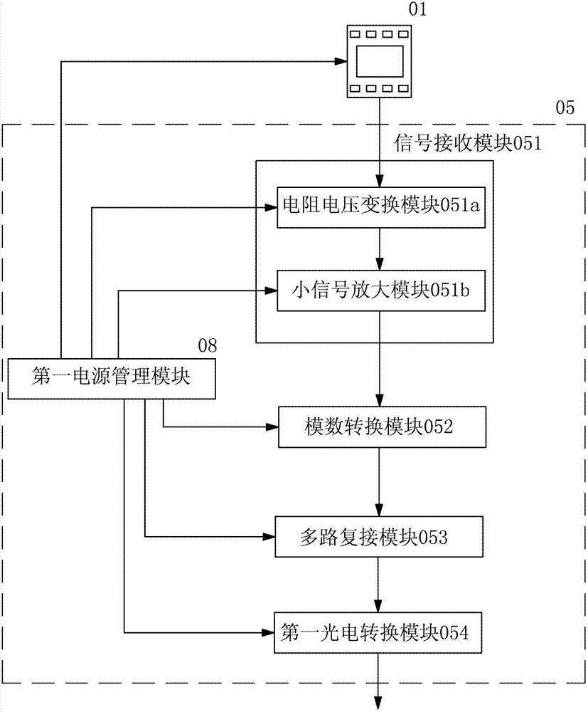
[0042] Step 2: Connect the resistance strain gauges arranged on the aircraft component nodes to the on-board signal processing module with wires, and the on-board signal processing module completes the signal acquisition of the real-time voltage value of each resistance strain gauge, signal analog-to-digital conversion, digital signal multiplexing, and digital signal processing. Photoelectric conversion and optical signal transmission;

[0043] Step 3: The monitoring and display module performs photoelectric conversion on the received optical signal, demultiplexes the real-time voltage data of each resistance strain gauge from the high-speed ...


PUM


Abstract

An airplane strength and strain detection method includes the steps as follows: an onboard signal processing module is arranged on an airplane, a monitoring display module is arranged in a monitoring chamber, and a data transmission passage is built between the onboard signal processing module and the monitoring display module through optical cables; resistance strain gages distributed on nodes of airplane members are connected to the onboard signal processing module through conducting wires, and the onboard signal processing module is used for signal acquisition, analog-digital conversion, digital signal multiple connection, signal photovoltaic conversion and optical signal transmission for real-time voltage values of the resistance strain gages; the monitoring display module is used for photovoltaic conversion for received optical signals, obtaining the real-time voltage data of the resistance strain gages from a high-speed digital signal flow through multiple connection, processing the voltage data into strength and strain data corresponding to the voltage data, and storing the data; and strength and strain data at the nodes of the members can be displayed in real time through patterns. The method realizes the high-speed multiway data and signal transmission, greatly simplifies the complexity of wiring and reduces the signal error. The invention further discloses an airplane strength and strain detecting system.

Description

technical field [0001] The invention relates to a method and system for detecting material structure, in particular to a method and system for detecting material strength and strain. Background technique [0002] The resistance value of the metal wire is not only related to the properties of the material, but also related to the length and cross-sectional area of ​​the metal wire. Paste the metal wire on the component. When the component is deformed by force, the length and cross-sectional area of ​​the metal wire also change with the component, and then the resistance changes. It can be seen that when the metal wire produces a strain effect, the strain amount has a linear relationship with the resistance change rate, which is the theoretical basis for using metal strain gauges to measure component strain. [0003] Such as figure 1 As shown, at present, the strain simulation monitoring under the condition of static load of the aircraft mostly uses resistance strain gauges....

Claims


Application Information

Patent Timeline
Patent Type & Authority Applications(China)
IPC IPC(8): G01B7/16G01N27/04G08C23/06
Inventor 陆兆辉
Owner 8TH RES INST OF CETC
Why Eureka
Try Eureka