Lens correction element, system and method

Inactive Publication Date: 2006-11-02
AGILENT TECH INC
View PDF4 Cites 35 Cited by
  • Summary
  • Abstract
  • Description
  • Claims
  • Application Information

AI Technical Summary

Benefits of technology

[0008] In accordance with another aspect of the present invention, a void disposed between two lenses or lens elements in a lens assembly is filled with a desired gas, liquid or vacuum, the gas, liquid or vacuum having a pre-determined index of refraction. Once the void has been filled with the desired gas, liquid or vacuum, the void is sealed by any of numerous appropriate means and preferably rendered leaktight. The lens assembly may then be tested or calibrated to ensure an appropriate level of optical performance prior to subsequent deployment under actual field conditions. Because the filled void disposed in the lens assembly provides optical performance that is index-of-refraction invariant, the lens assembly may be employed successfully under widely varying atmospheric conditions and yet still provide high quality results.

Problems solved by technology

In such environments, the performance of optical assemblies such as collimators incorporated into DMIs calibrated for operation at sea-level may be affected negatively due to changes in the indices of refraction of gases positioned between lenses in such assemblies caused by elevation, altitude and / or atmospheric pressure changes.
Unexpectedly large changes in atmospheric pressure in the field may also lead to poor optical performance of a lens assembly that has been calibrated under laboratory conditions.
Testing optical assemblies incorporated into DMIs under vacuum conditions, however, may require considerable expense and time.
Moreover, unwitting failure to achieve a perfect vacuum, or other mistakes made during laboratory testing, may lead to improper operation in the field that may not be discovered until after the optical system has been deployed, when it may no longer be possible to make corrections.
Such a solution, however, requires that the lens assembly be physically manipulated once it has been placed in the second medium, a task that may entail considerable expertise and expense, especially if the second medium happens to be the vacuum of outer space.

Method used


Image

  • Lens correction element, system and method
  • Lens correction element, system and method
  • Lens correction element, system and method

Examples


Embodiment Construction

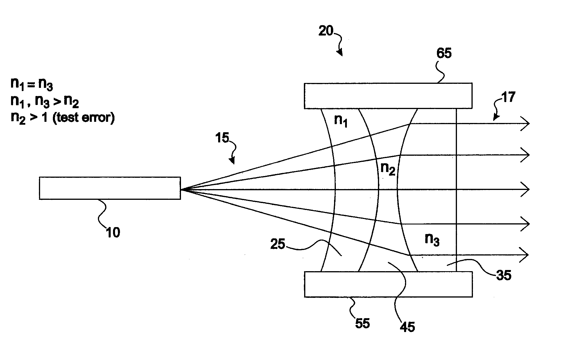
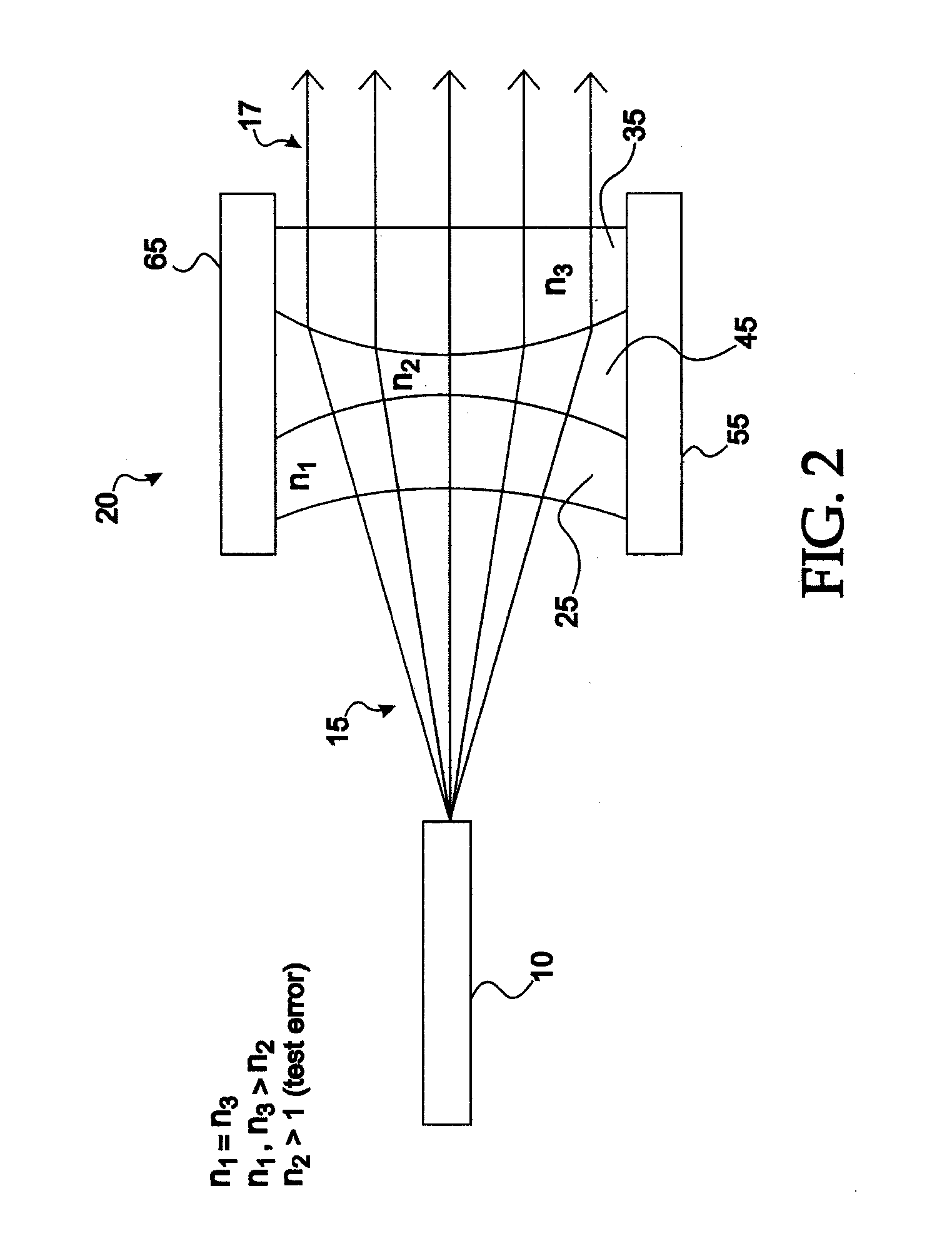
[0023] As employed in the specification, drawings and claims hereof, the term “lens assembly 10” or “lens assembly” means a lens assembly employed for beam collimation, reduction and / or enlargement in DMI, laser, optical, communications, photographic, telephony or other applications. The term is not intended to be limited to DMI applications, which are used here for descriptive and illustrative purposes only. After having read and understood the present specification, drawings and claims hereof, those skilled in the art will understand that various embodiments of the present invention may be employed in many applications beyond distance measuring interferometers.

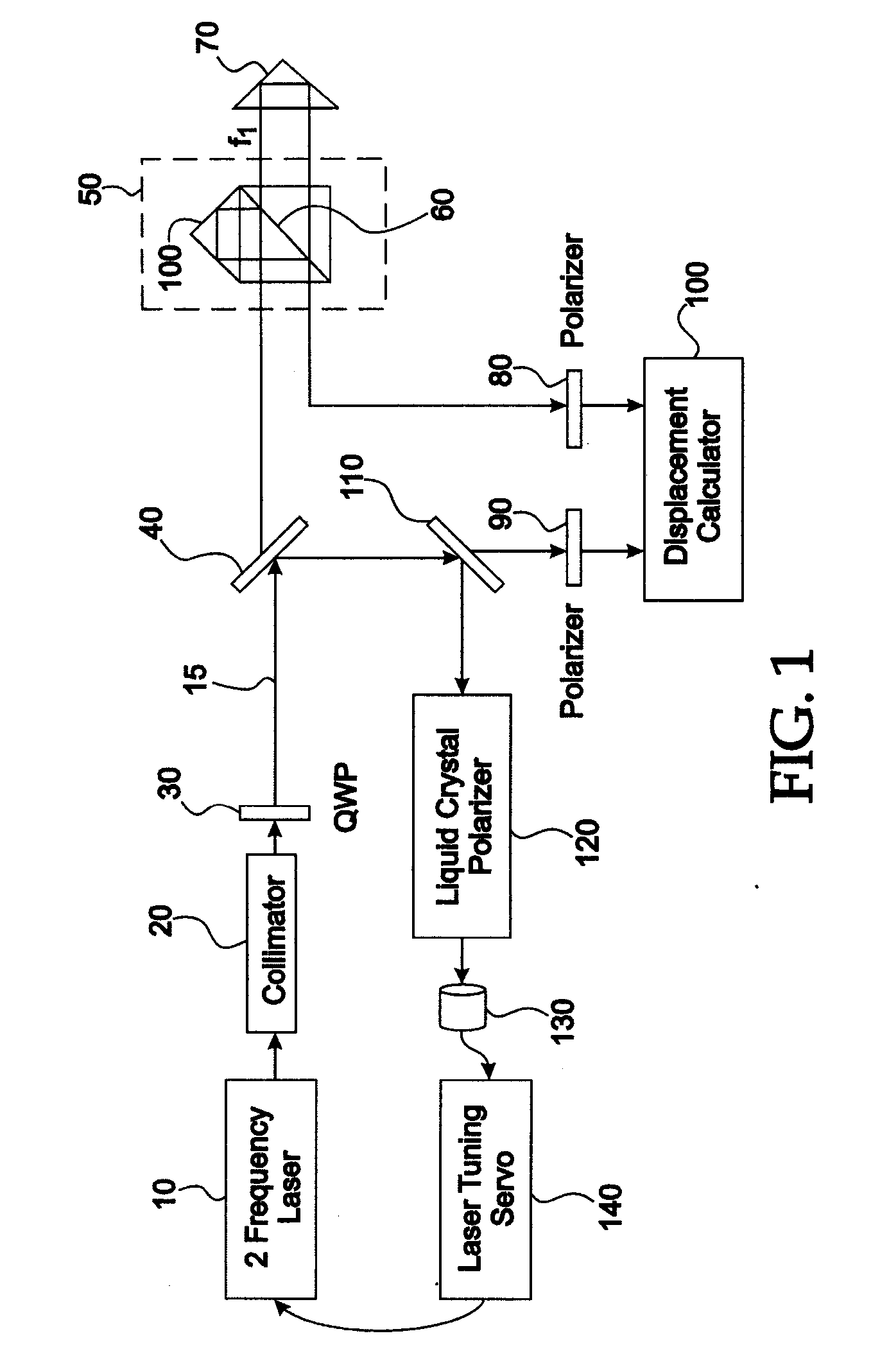
[0024]FIG. 1 shows a block diagram of a DMI system, and depicts portions of an Agilent Model Number 10705 Linear Interferometer system. Telescope or collimator 20 includes a lens assembly 20 (not shown in FIG. 1) for enlarging the diameter of the laser beam emitted by source 10 from 1 mm to 9 mm. The diameter of the laser b...


PUM


Abstract

A lens assembly is provided that has an index-of-refraction invariant structure. In one embodiment, a void between two lenses or lens elements in a lens assembly is filled with a desired gas, liquid or vacuum, the gas, liquid or vacuum having a pre-determined index of refraction. Once the void has been filled with the desired gas or liquid or been drawn down to a complete vacuum, the void is sealed by any of numerous appropriate means to render it leaktight. The lens assembly may then be tested or calibrated to ensure an appropriate level of optical performance prior to subsequent deployment under actual field conditions. Because the vacuum or filled void disposed in the lens assembly provides optical performance that is index-of-refraction invariant, the lens assembly may be employed successfully under widely varying atmospheric conditions and yet still provide the same high quality results.

Description

BACKGROUND [0001] Displacement measuring interferometers (“DMIs”) are well known in the art, and have been used to measure small displacements and lengths to high levels of accuracy and resolution for several decades. Many types of DMIs include optical systems that appropriately collimate light emitted by laser sources prior to delivery to an interferometer assembly. [0002] In one typical DMI application, an optical “telescope” or collimator assembly is disposed between the output provided by a helium-neon laser source and an interferometer assembly. Such a telescope or collimator typically includes a lens assembly for enlarging the diameter of the laser beam emitted by source. The enlarged beam reduces beam walk-off errors arising from rotational or translational movement of portions of the interferometry system. [0003] Occasionally DMIs are employed in unusual environments, such in a vacuum, at high-altitude or in outer space. In such environments, the performance of optical assem...

Claims


Application Information

Patent Timeline
IPC IPC(8): G02B3/12
CPCG02B3/12
Inventor GEORGE, DAVID M.SCHLUCHTER, WILLIAM CLAYBELT, ROBERT TODD
Owner AGILENT TECH INC
Why Eureka
Try Eureka