Steam turbine power plant

a steam turbine and power generation technology, applied in the direction of machines/engines, stators, liquid fuel engines, etc., can solve the problems of poor workability, economic efficiency, and productivity of ni base alloys and austenite-based materials, and achieve the effects of improving thermal efficiency, ensuring reliability, operability and economic efficiency

Active Publication Date: 2006-11-02
KK TOSHIBA
View PDF4 Cites 10 Cited by
  • Summary
  • Abstract
  • Description
  • Claims
  • Application Information

AI Technical Summary

Benefits of technology

[0016] According to this steam turbine power plant, the nozzle box of the extra-high-pressure turbine is formed of the heat-resisting alloy having the above-described chemical composition range, the turbine rotor which is cooled by the turbine rotor cooling unit is formed of the heat-resisting steel having the above-described chemical composition range, and the inner casing which is cooled by the inner casing cooling unit and the outer casing which is cooled by the outer casing cooling unit are formed of the cast steel havi

Problems solved by technology

But, in a case where the power generation efficiency is improved by raising the steam temperature of the steam turbine to, for example, 650° C. or more, it is hard to apply the structure of a conventional steam turbine power generation system as it is in view of the mechanical characteristics and environment resistance because the conventional steam turbine power generation system uses a ferrite-based heat-resisting steel for the main members such as a nozzle, a turbine rotor, a casing and the like o

Method used


Image

  • Steam turbine power plant
  • Steam turbine power plant
  • Steam turbine power plant

Examples


first embodiment

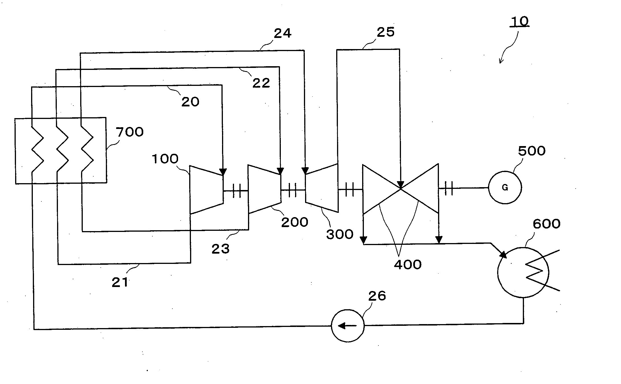
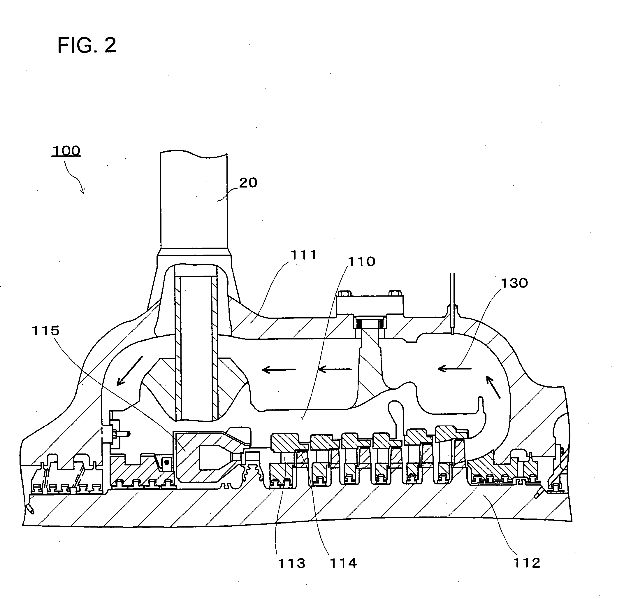
[0024]FIG. 1 shows schematically an overview of a steam turbine power generation system 10 of a first embodiment. FIG. 2 shows a sectional view of an upper-half casing portion of an extra-high-pressure turbine 100.

[0025] The overview of the steam turbine power generation system 10 will be described with reference to FIG. 1.

[0026] The steam turbine power generation system 10 is mainly comprised of the extra-high-pressure turbine 100, a high-pressure turbine 200, an intermediate-pressure turbine 300, a low-pressure turbine 400, a generator 500, a condenser 600, and a boiler 700.

[0027] Subsequently, an operation of steam in the steam turbine power generation system 10 will be described.

[0028] Steam which is heated to a temperature of 650° C. or more in the boiler 700 is flown into the extra-high-pressure turbine 100 through a main steam pipe 20. Where the moving blades of the extra-high-pressure turbine 100 are configured in, for example, seven stages, the steam having performed an...

example 1

[0086] Table 1 shows chemical compositions of materials (material PA1 through material PA4) configuring the turbine rotor 112, the inner casing 110 and the nozzle box 115, and chemical compositions of materials (material CA1 through material CA4) as comparative examples which are not in the ranges of the chemical compositions according to the invention. Here, as the material configuring the turbine rotor 112, the material PA1 and the material PA2 are used, and as the material configuring the inner casing 110 and the nozzle box 115, the material PA3 and the material PA4 are used. The material PA1 and the material PA2 are configured of the heat-resisting alloy having the chemical composition range of the material (M1) configuring the above-described turbine rotor 112, and the material PA3 and the material PA4 are configured of the heat-resisting alloy having the chemical composition range of the material (M2) configuring the above-described inner casing 110 and the nozzle box 115.

[00...

example 2

[0092] Table 3 shows chemical compositions of a material (material PS1) configuring the outer casing 111, and as a comparative example, chemical compositions of a material (material CS1) which is not in the range of chemical compositions according to the invention. The material PS1 is comprised of a cast steel having the range of the chemical compositions of the material (M3) configuring the above-described outer casing 111.

[0093] The material PS1 and the material CS1 undergone a prescribed heat treatment were heated at 600° C. for 10,000 hours and measured for a room-temperature 0.02% proof stress, an absorbed energy at 20° C. and a creep rupture strength at 600° C. for 100,000 hours.

[0094] Table 4 shows values obtained by dividing the values after heating in the individual measurements by the values before heating. Here, a value obtained by dividing the room-temperature 0.02% proof stress after heating at 600° C. for 10,000 hours by a room-temperature 0.02% proof stress before h...


PUM

PropertyMeasurementUnit
Temperatureaaaaaaaaaa
Currentaaaaaaaaaa

Abstract

A steam turbine power plant which is provided with an extra-high-pressure turbine 100, a high-pressure turbine 200, an intermediate-pressure turbine 300 and a low-pressure turbine 400, and has high-temperature steam of 650° C. or more introduced into the extra-high-pressure turbine 100, wherein the extra-high-pressure turbine 100 has an outer casing cooling unit which cools an outer casing 111, and a turbine rotor 112, an inner casing 110 and a nozzle box 115 of the extra-high-pressure turbine 100 are formed of an Ni base heat-resisting alloy, and the outer casing 111 is formed of a ferrite-based alloy.

Description

CROSS-REFERENCE TO RELATED APPLICATIONS [0001] This application is based upon and claims the benefit of priority from the prior Japanese Patent Application No. 2005-130966 filed on Apr. 28, 2005; the entire contents of which are incorporated herein by reference. BACKGROUND [0002] 1. Field of the Invention [0003] The present invention relates to a steam turbine power plant provided with a high-temperature steam turbine, and more particularly to a steam turbine power plant provided with a steam turbine which has individual configuration portions formed of a suitable heat-resisting alloy, a heat-resisting steel or the like. [0004] 2. Description of the Related Art [0005] Energy saving of the thermal power system is being performed vigorously after the energy crisis, generation of CO2 is being suppressed and needs for high efficiency are increasing in view of the global environmental protection in these years. [0006] The conventional steam turbine power generation systems have a steam t...

Claims


Application Information

Patent Timeline
IPC IPC(8): F01D25/26
CPCF01D25/26F01K7/22F01K7/16
Inventor SUGA, TAKEOISHII, RYUICHITAKAHASHI, TAKEOFUKUDA, MASAFUMI
Owner KK TOSHIBA
Why Eureka
Try Eureka