Pump

a technology of pump and pump chamber, applied in the field of pumps, can solve the problems of insufficient rise of the inside of the pump chamber, inability to discharge fluid, performance degradation,

Inactive Publication Date: 2006-11-02
SEIKO EPSON CORP
View PDF12 Cites 47 Cited by
  • Summary
  • Abstract
  • Description
  • Claims
  • Application Information

AI Technical Summary

Benefits of technology

[0044] According to the aforementioned configuration, a change in a volume etc. of a pump chamber can be easily carried out to meet with various specifications.

Problems solved by technology

In the case of a configuration in Nonpatent Document 1, a problem has existed wherein, in the event that air bubbles enter the pump, even though the pump capacity is changed, the pressure inside the pump chamber does not rise sufficiently due to the effect of the air bubbles, the performance deteriorates and, in the event that more than a certain amount of air bubbles enter the pump, discharge of the fluid becomes impossible.
In the case of the kind of air bubble removal device in Patent Document 1, although it is possible to carry out removal of the air bubbles in the working fluid by installing the device in a channel inside a circulatory liquid cooling device of a closed electronic instrument such as a cooling system, thereby reducing the inflow of air bubbles to the pump chamber, there has been no benefit with respect to air bubbles which have entered the pump chamber.
The pump in Patent document 2 has been designed to prevent the coagulation of blood caused by accumulation, and has not generated a rotational flow sufficient for the elimination of air bubbles.

Method used


Image

  • Pump
  • Pump
  • Pump

Examples


first embodiment

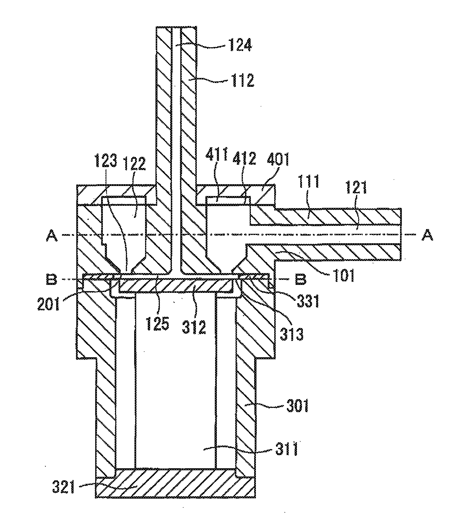
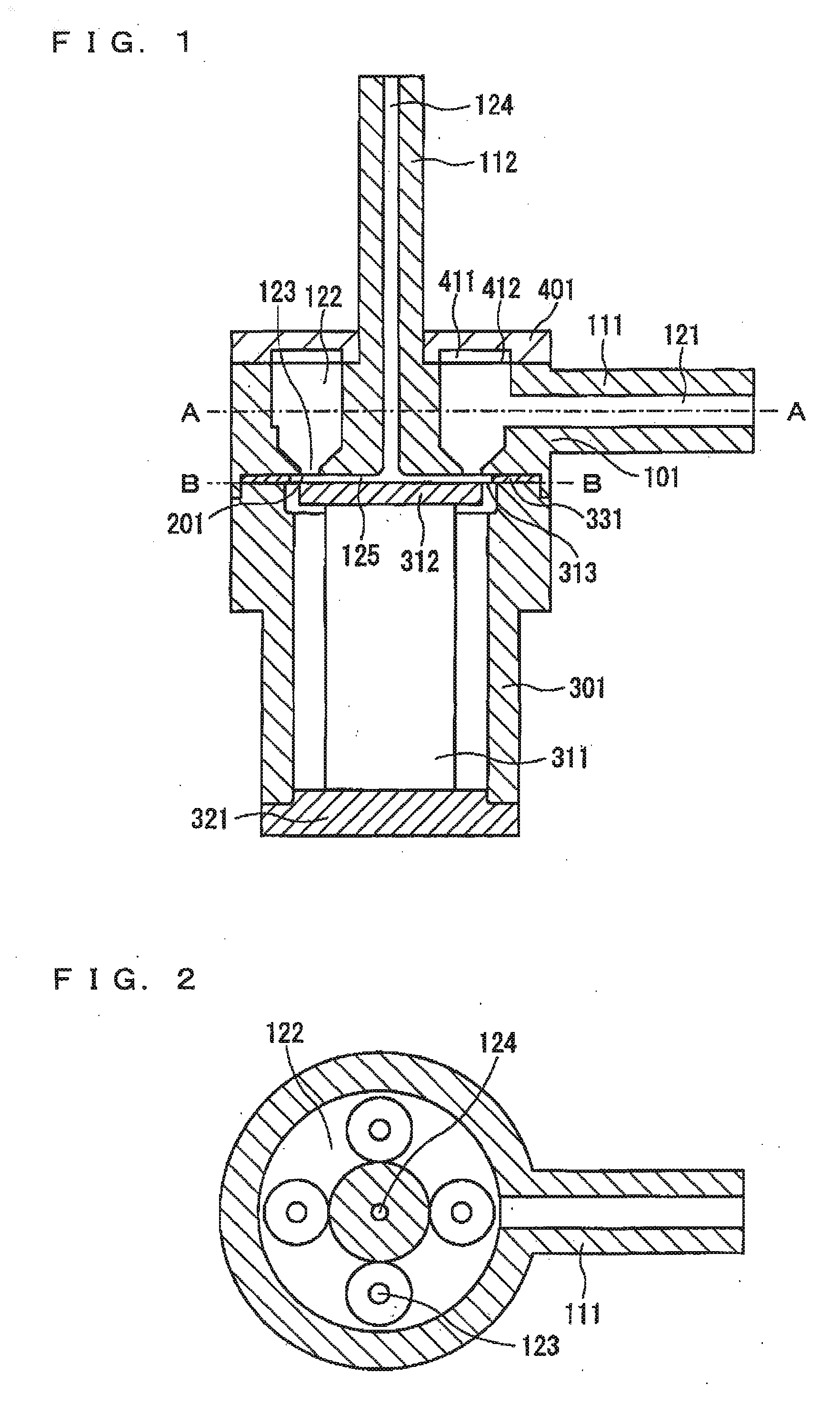
[0060] First, a description will be given, with reference to FIG. 1, of a pump configuration according to a first embodiment of the invention. FIG. 1 shows a vertical cross-section of a pump according to the first embodiment of the invention. FIG. 2, being a top view of a film protective cover 401 and an annular resin film 412, attached to the upper surface of the pump shown in FIG. 1, in a state removed from the pump, is a cross-sectional view taken along line A-A in FIG. 1. A bottom plate 321 is secured to the bottom of a cylindrically-configured casing 301, and a laminated type piezoelectric element 311 is secured to the upper surface of the bottom plate 321. A reinforcement plate 312 is secured to the upper surface of the laminated type piezoelectric element 311, while a diaphragm 313 is secured to both the upper surface of the reinforcement plate 312 and a rim of the casing 301.

[0061] Above the diaphragm 313, a channel member 101 is affixed, by a not-shown screw, to the casing...

second embodiment

[0094] Next, a description will be given of a second embodiment.

[0095] As a structure of a pump according to the second embodiment (refer to FIG. 1) has many parts in common with the structure of the pump in the first embodiment, the common parts are given like reference numerals etc., the descriptions are omitted, and the description hereafter focuses on the differences.

[0096] In the structure of the pump, a rotational flow generation structure and a structure of a check valve, which acts as a fluid resistance element, are different.

[0097]FIGS. 8A and 8B are sectional side views showing a valve operation. As in the first embodiment, a pump chamber is formed in the bottom of the channel member 101. An inclined channel 223 is hollowed out so as to be inclined with respect to the bottom surface of the channel member 101, wherein a check valve unit, comprising a valve seat 221 and a ball 222, is press fitted inside the inclined channel 223.

[0098] The valve seat 221 is structured to...

third embodiment

[0109] Next, a description will be given of a third embodiment.

[0110] As a structure of a pump according to the third embodiment (refer to FIG. 1) also has many parts in common with the configuration of the pump in the first embodiment, the common parts are given like reference numerals etc., the descriptions are omitted, and the description hereafter focuses on the differences.

[0111] The pump according to the third embodiment differs from the pump according to the first embodiment in that a forced flow portion (a flow speed increase section) is provided which accelerates a flow speed of the working fluid in the pump chamber 125.

[0112]FIG. 12 shows a vertical section of the pump according to the third embodiment. Also, FIG. 13 is a cross-sectional view taken along line C-C in FIG. 12.

[0113] As shown in FIG. 13, the pump according to the third embodiment is equipped with an annular member 341, which has an outer chamber 342 surrounding the pump chamber 125, instead of the annular...


PUM


Abstract

A pump includes: a pump chamber for which a capacity is changeable; an inlet channel which allows a working fluid to flow into the pump chamber; an inlet side fluid resistance element disposed between the pump chamber and the inlet channel; an outlet channel which allows the working fluid to flow out of the pump chamber; and a pipeline element formed inside the outlet channel, wherein a rotational flow generation structure, which generates a rotational flow of the working fluid, is provided in the pump chamber, and wherein the outlet channel is located adjacent to the rotational center of the rotational flow.

Description

BACKGROUND [0001] 1. Technical Field [0002] The present invention relates to a pump which carries out a movement of a working fluid by changing a capacity inside a pump chamber by means of a piston, a diaphragm or the like, and in particular to a compact, high-output pump. [0003] 2. Related Art [0004] Until now, with a configuration of replacing a check valve of an outlet channel with a channel structure having a large inertance value, using an inertia effect of a fluid, a highly-reliable high-output pump with a large discharge flow volume corresponding to a high load pressure has been developed by the inventors of the invention. (Refer to Nonpatent Document 1: “A high-output micro pump using an inertia effect of a fluid” Japan Mechanical Society Journal 2003.10 VOL. 106 No. 1019 (Page 823, FIGS. 1 to 5)). [0005] Also, in a fluid system which has as a fluid drive source a pump, such as a centrifugal pump, having a liquid as a working fluid, whose pumping capability deteriorates in t...

Claims


Application Information

Patent Timeline
Patent Type & Authority Applications(United States)
IPC IPC(8): F04B35/04
CPCF04B17/003F04B43/04F04B53/16F04B53/1002F04B53/105F04B43/046
Inventor SETO, TAKESHITAKAGI, KUNIHIKO
Owner SEIKO EPSON CORP
Why Eureka
Try Eureka