Catalytic thermal barrier coatings

a thermal barrier coating and catalytic technology, applied in the direction of catalytic material combustion, combustion types, separation processes, etc., can solve the problem of increasing the temperature of both the catalyst and the catalyst substrate, the operating temperature limit of the underlying metal substrate material, and the environment of the gas turbine is very hostil

Inactive Publication Date: 2006-11-02
SIEMENS ENERGY INC
View PDF64 Cites 68 Cited by
  • Summary
  • Abstract
  • Description
  • Claims
  • Application Information

AI Technical Summary

Problems solved by technology

However, increasing the amount of combustion on the catalyst surface will also increase the temperature of both the catalyst and the catalyst substrate.
One of the limitations to increasing the amount of combustion in the catalytic reactor 12 is the operating temperature limit of the underlying metal substrate material.
The operating environment of a gas turbine is very hostile to c

Method used


Image

  • Catalytic thermal barrier coatings
  • Catalytic thermal barrier coatings

Examples


Embodiment Construction

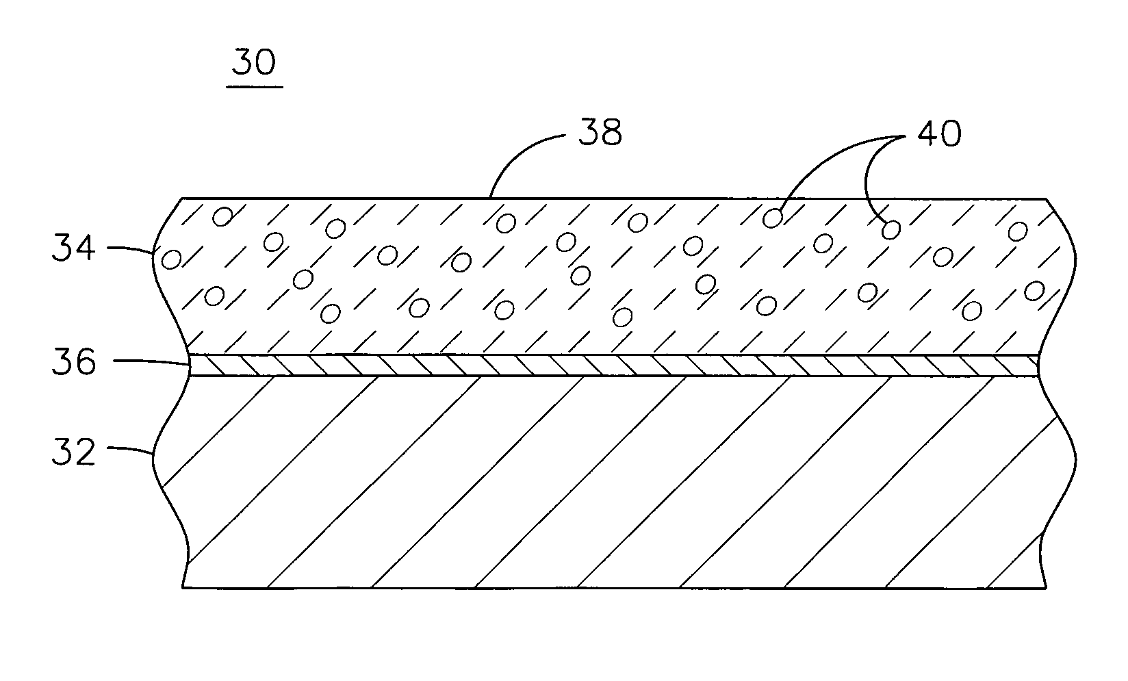
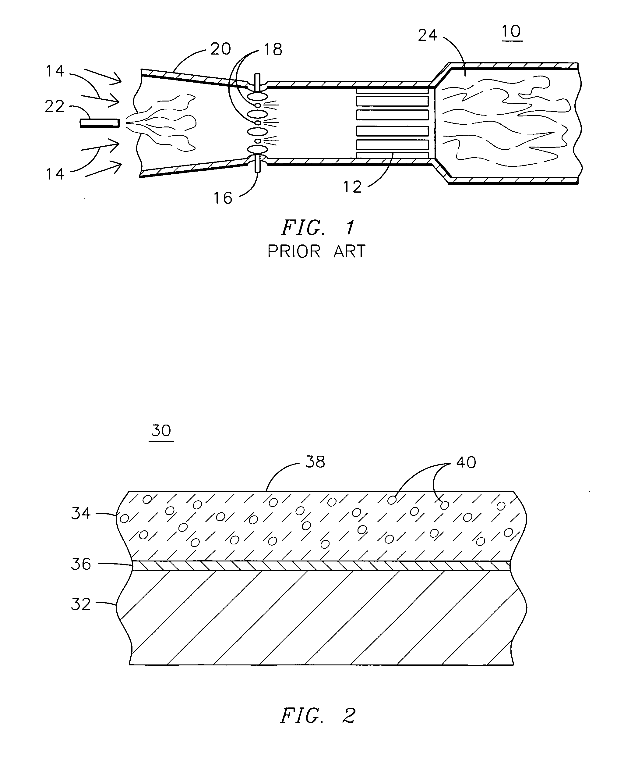
[0010] Traditional catalytic systems incorporate an active precious metal catalyst such as palladium on a γ-Al2O3 washcoat. The present inventors have found such systems to exhibit poor phase stability, surface area loss, and rapid surface diffusion causing catalyst agglomeration at the very high temperatures desired for modern gas turbine engine designs. For example, the γ-Al2O3 phase having a specific surface area (SSA) value of 125-250 m2 / g transforms to either θ or δ phase with an SSA value of 18-30 m2 / g at 450° C., which then transforms to α phase with an SSA value of 5 m2 / g between 900-1100° C. To solve these problems, the present inventors have innovatively modified ceramic thermal barrier coating (TBC) materials that are known to exhibit acceptable high temperature insulating characteristics with ionic substitutions that serve to improve the catalytic activity of the materials. In certain embodiments, the inventors have also incorporated precious metal crystallites into the ...


PUM

PropertyMeasurementUnit
Specific surface areaaaaaaaaaaa

Abstract

A catalyst element (30) for high temperature applications such as a gas turbine engine. The catalyst element includes a metal substrate such as a tube (32) having a layer of ceramic thermal barrier coating material (34) disposed on the substrate for thermally insulating the metal substrate from a high temperature fuel/air mixture. The ceramic thermal barrier coating material is formed of a crystal structure populated with base elements but with selected sites of the crystal structure being populated by substitute ions selected to allow the ceramic thermal barrier coating material to catalytically react the fuel-air mixture at a higher rate than would the base compound without the ionic substitutions. Precious metal crystallites may be disposed within the crystal structure to allow the ceramic thermal barrier coating material to catalytically react the fuel-air mixture at a lower light-off temperature than would the ceramic thermal barrier coating material without the precious metal crystallites.

Description

RELATED APPLICATIONS [0001] This application is a continuation-in-part of U.S. patent application Ser. No. 09 / 963,283 filed on 26 Sep. 2001, which is incorporated by reference herein.GOVERNMENT INTEREST [0002] This invention was made with United States Government support through Contract Number DOE-DE-FC26-03NT41891 awarded by the Department of Energy, and, in accordance with the terms set forth in that contract, the United States Government may have certain rights in the invention.FIELD OF THE INVENTION [0003] This invention relates generally to the field of catalytic combustion, and more specifically to catalytic combustion in a gas turbine engine environment. BACKGROUND OF THE INVENTION [0004] In the operation of a conventional gas turbine engine, intake air from the atmosphere is compressed and heated by a compressor and is caused to flow to a combustor, where fuel is mixed with the compressed air and the mixture is ignited and burned. The heat energy thus released then flows in...

Claims


Application Information

Patent Timeline
IPC IPC(8): B01D50/00F23C13/00F23R3/40
CPCF23C13/00F23R3/40F23C13/08
Inventor KULKARNI, ANAND A.CAMPBELL, CHRISTIAN X.SUBRAMANIAN, RAMESH
Owner SIEMENS ENERGY INC
Why Eureka
Try Eureka