Gas distribution panel for a fuel cell and gas distribution panel containing a fuel cell
- Summary
- Abstract
- Description
- Claims
- Application Information
AI Technical Summary
Benefits of technology
Problems solved by technology
Method used
Image

Examples
Embodiment Construction
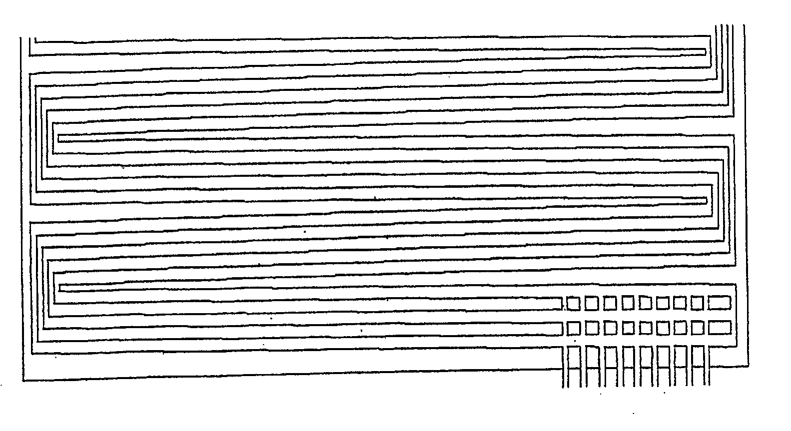
[0013] The subject matter of the invention is thus a gas distribution panel for a fuel cell, in which gas supply channels which run parallel are arranged with a meandering structure, characterized in that ribs or webs with a varying width are provided on the meander boundary channels in order to reduce the lateral transport of media along the meander boundary channels.
[0014] The subject matter of the invention is also a fuel cell having a gas distribution panel such as this on the cathode side and / or anode side.
[0015] According to the invention, it has thus been found that the object mentioned above can be achieved in that the width of the web which is provided at the relevant junctions in the gas supply channels is varied in such a way that the lateral flow that occurs is just enough to allow an adequate reactant concentration in the reaction zone above the relevant web section.
[0016] According to the invention, two configurations are provided for the variation of the web width ...
PUM
 Abstract
Description
Claims
Application Information