
Testable digital delay line

Inactive Publication Date: 2006-11-02
IBM CORP
View PDF4 Cites 16 Cited by
  • Summary
  • Abstract
  • Description
  • Claims
  • Application Information

AI Technical Summary

Benefits of technology

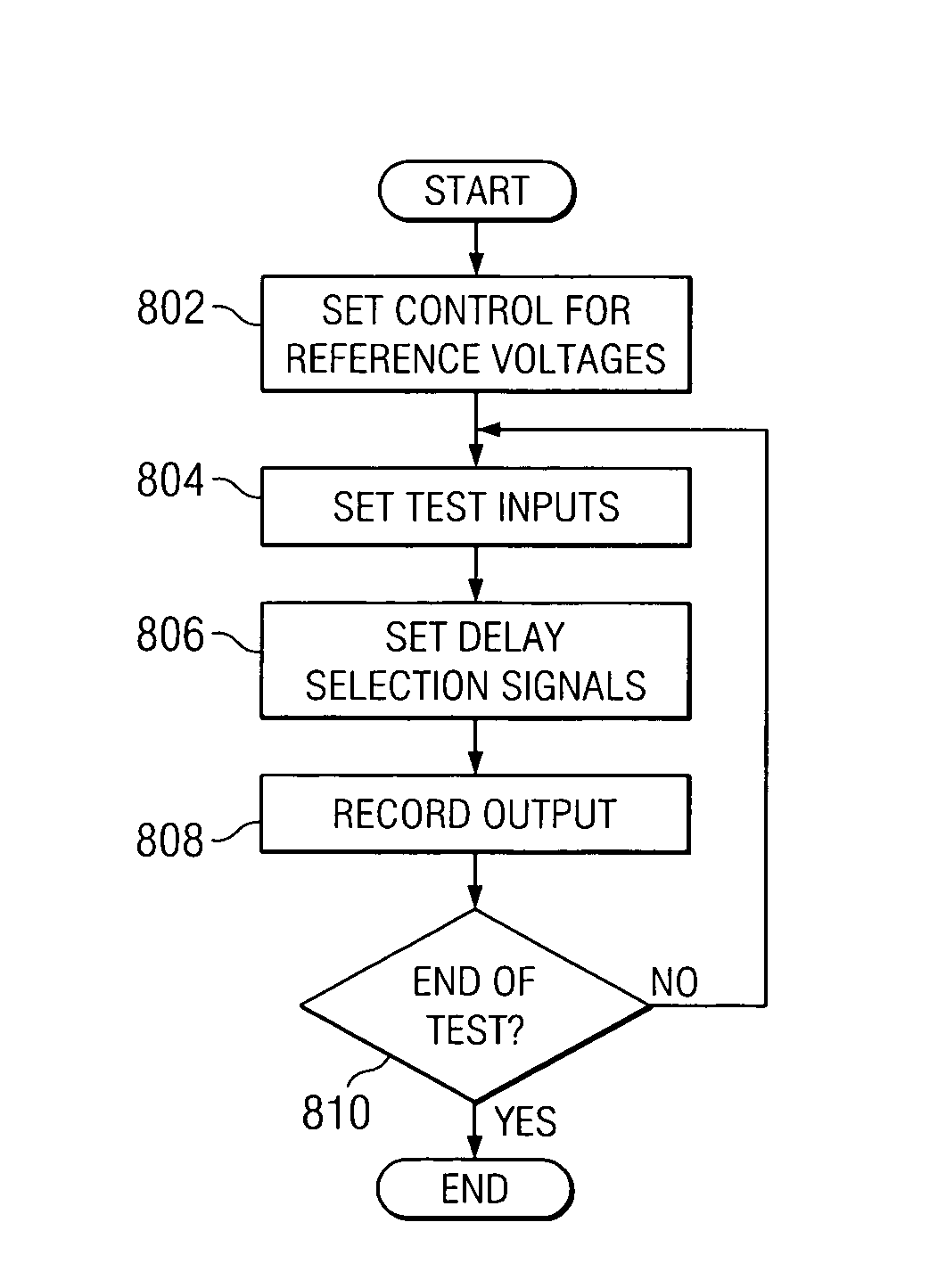
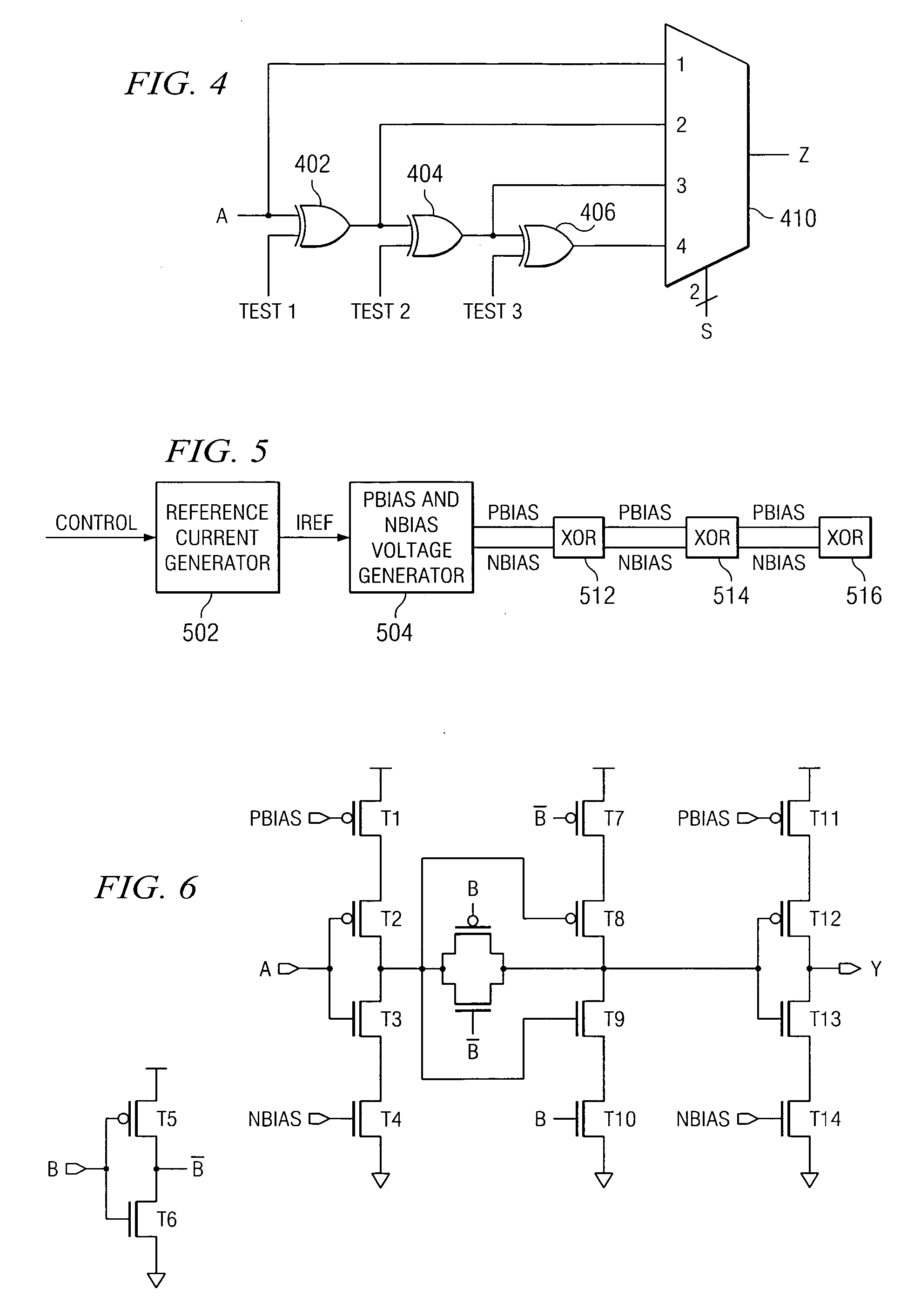
[0008] The present invention recognizes the disadvantages of the prior art and provides a testable digital delay line that uses XOR gates as delay elements. The use of XOR gates enables independent control of each input to the multiplexer. With test inputs that enable each delay element, the multiplexer inputs can be assigned any value during test, thus giving the delay line very robust pattern fault coverage. The XOR gate may consist of three current limiting inverters. A reference voltage generator generates constant voltages between a source voltage, bias voltages, and ground. These constant voltages decide the amount of current through the current limiting inverters. Selecting a different set of reference voltages programs a different current flowing in the current limiting inverters. This programmable current causes a programmable unit delay to be introduced by each XOR gate delay element.

Problems solved by technology

Due to process variations and other design constraints, this is not always the case.
These linear delay stepping devices occupy a huge amount of chip area and, therefore, are susceptible to structural defects during the manufacturing process.
A primary cause of non testability comes from a pattern fault model for the delay element selection multiplexer.
Even when one of the inputs is selected, other another input might have an effect on the output based upon weak coupling due to an improperly manufactured device.
This is the expected operation during functional mode; however, during a static fault test at wafer level, this circuit cannot be tested for pattern faults.
This inability to verify the design for pattern faults reduces the testability coverage.
Reduction in testability coverage leads to poor diagnostics in case of the lower yields.

Method used


Image

  • Testable digital delay line
  • Testable digital delay line
  • Testable digital delay line

Examples


Embodiment Construction

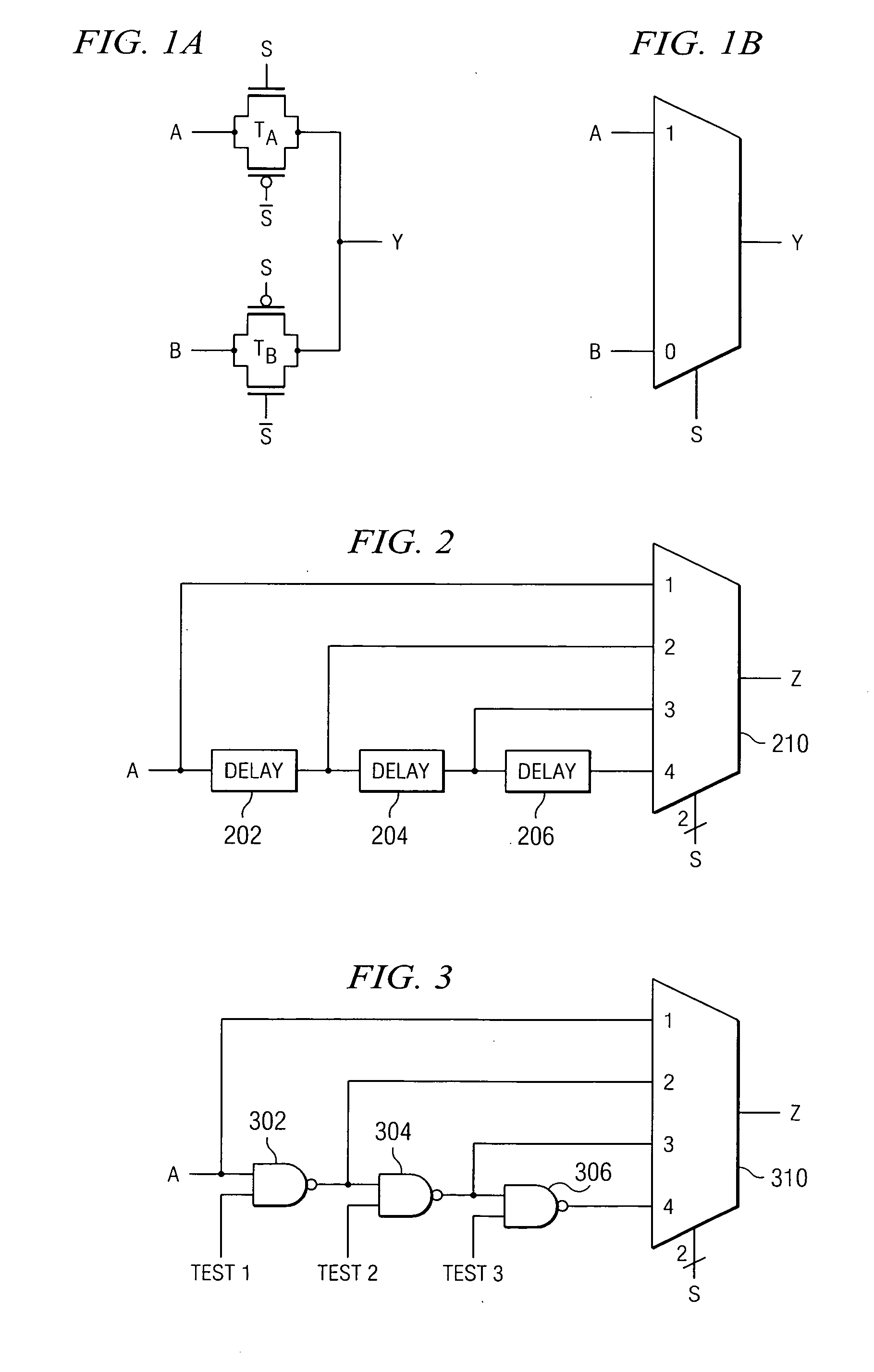
[0018] A method and apparatus for providing a testable delay line are provided. The following FIGS. 1-3 are provided as exemplary diagrams of important aspects of digital delay lines to which the exemplary aspects of the present invention may be applied. It should be appreciated that FIGS. 1-3 are only exemplary and are intended only to illustrate the aspects of digital delay lines to which the exemplary aspects of the present invention may be applied. Many modifications to digital delay line environments may be made without departing from the spirit and scope of the exemplary embodiments described herein.

[0019] With reference now to the figures and in particular with reference to FIGS. 1A and 1B, a pictorial representation of a multiplexer constructed using transmission gates wired together to which the exemplary aspects of the present invention may be applied. As shown in FIG. 1A, input A is connected to transmission gate TA and input B is connected to transmission gate TB. Selec...


PUM


Abstract

A testable digital delay line that uses XOR gates as delay elements is provided. The use of XOR gates enables independent control of each input to the multiplexer. With test inputs that enable each delay element, the multiplexer inputs can be assigned any value during test, thus giving the delay line very robust pattern fault coverage. The XOR gate may consist of three current limiting inverters. A reference voltage generator generates constant voltages between a source voltage, bias voltages, and ground. These constant voltages decide the amount of current through the current limiting inverters. Selecting a different set of reference voltages programs a different current flowing in the current limiting inverters. This programmable current causes a programmable unit delay to be introduced by each XOR gate delay element.

Description

BACKGROUND OF THE INVENTION [0001] 1. Technical Field [0002] The present invention relates to signal delay devices for integrated circuits and, in particular, to testability of digital delay lines. [0003] 2. Description of Related Art [0004] Delay elements perform the function of delaying a signal in accordance with a control signal. For proper functioning of synchronous circuits, it is important for data to arrive at the right time relative to a clock signal. Due to process variations and other design constraints, this is not always the case. Digital delay lines are commonly employed to compensate for variations in design and fabrication. Digital delay lines provide a mechanism for adding a set amount of delay into the receipt of a signal. [0005] As the chip sizes grow, the requirements for delay compensation also grow. These linear delay stepping devices occupy a huge amount of chip area and, therefore, are susceptible to structural defects during the manufacturing process. It is ...

Claims


Application Information

Patent Timeline
IPC IPC(8): G01R31/00
CPCG01R31/31725H03K2005/00156H03K2005/00039
Inventor KAPUR, MOHITKIM, SEONGWON
Owner IBM CORP
Learn More