Radiation image pickup device

a technology of radio frequency and image, which is applied in the direction of radio frequency controlled devices, color television, television systems, etc., can solve the problems of reducing the saturation output of the sensor, forming unnecessary parasitic capacity, and reducing the dynamic range of the sensor, so as to achieve the effect of improving sensitivity

Inactive Publication Date: 2006-11-09
CANON KK
View PDF6 Cites 86 Cited by
  • Summary
  • Abstract
  • Description
  • Claims
  • Application Information

AI Technical Summary

Benefits of technology

[0013] The present invention has been made in the light of the foregoing problems, and it is, therefore, an object of the present invention to make it possible that even when an electric potential of a separate electrode of a sensor element disposed above a TFT element fluctuates, the fluctuation in characteristics due to generation of a leakage current of the TFT element is suppressed to attain enhancement of sensitivity.
[0015] According to the present invention, the top gate structure is adopted for the TFT element to thereby obtain such a structure that a TFT channel portion is protected by a gate electrode without disposing a complicated shielding structure above the TFTs. As a result, it is possible to obtain stable TFT characteristics without turning ON any of the TFT elements due to the back gate effect caused by the fluctuation in electric potentials corresponding to outputs from the sensor electrodes. That is to say, it is possible to greatly improve image quality as well.

Problems solved by technology

In addition, it is described that since the TFT element is disposed right under the sensor element, an unnecessary parasitic capacity is formed, and hence a grounded plane is disposed.
Thus, a problem such as generation of a leakage current of the TFT element is caused due to the fluctuation in electric potential of the separate electrode to cause degradation in image quality.
In addition, there is caused a problem that a sensor saturation output is decreased to reduce a dynamic range.

Method used


Image

  • Radiation image pickup device
  • Radiation image pickup device
  • Radiation image pickup device

Examples


embodiment 1

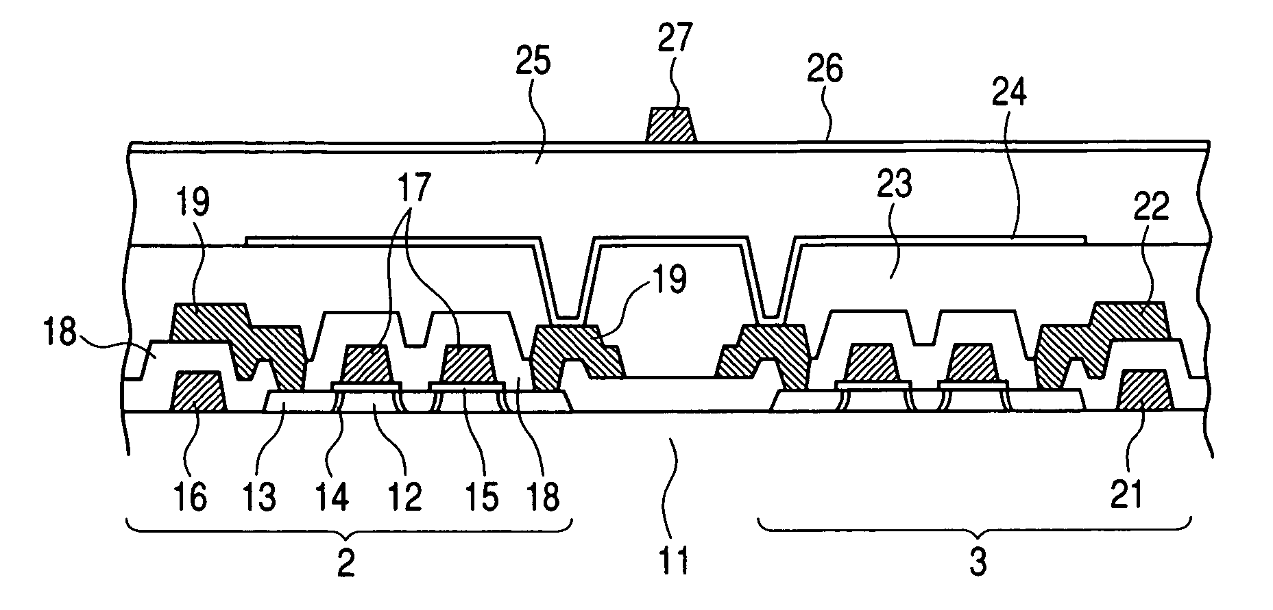
[0038] A photoelectric converter in which transferring TFT elements and resetting TFT elements are disposed in pixels, respectively, and a radiation image pickup device will now be described as Embodiment 1 of the present invention. Embodiment 1 relates to an indirect type radiation image pickup device in which a wavelength conversion unit for wavelength-converting radiation into light such as visible light is disposed above a photoelectric converter, and the resultant light is read out by the photoelectric converter. Either an MIS type PD or a PIN type PD may be used for the photoelectric conversion element of the photoelectric converter.

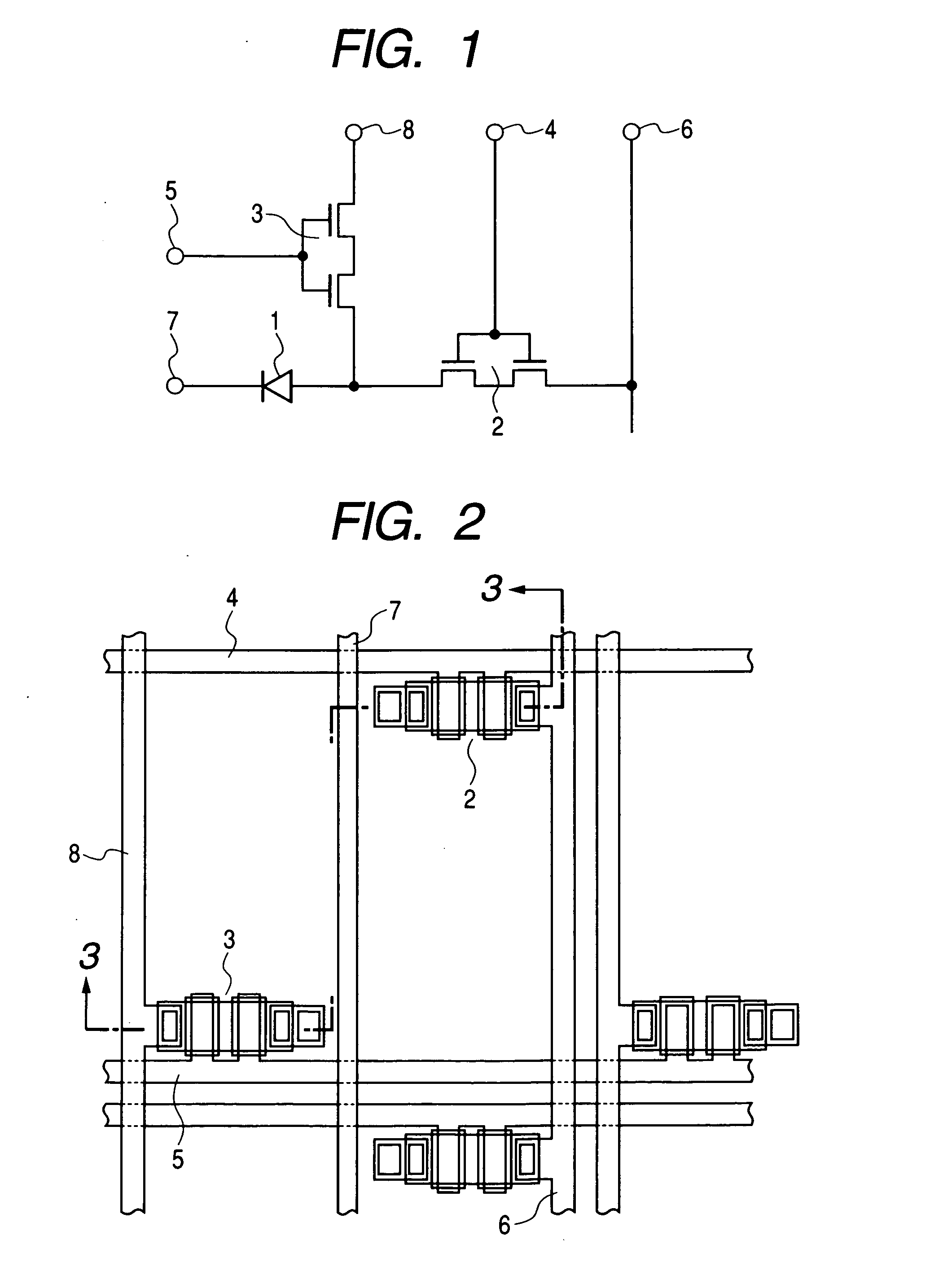
[0039]FIG. 1 shows an equivalent circuit diagram of 1 bit (one pixel) in the photoelectric converter. In the figure, reference numeral 1 designates a photoelectric conversion element portion; reference numeral 2 designates a transferring TFT portion; reference numeral 3 designates a resetting TFT portion; reference numeral 4 designates a transferr...

embodiment 2

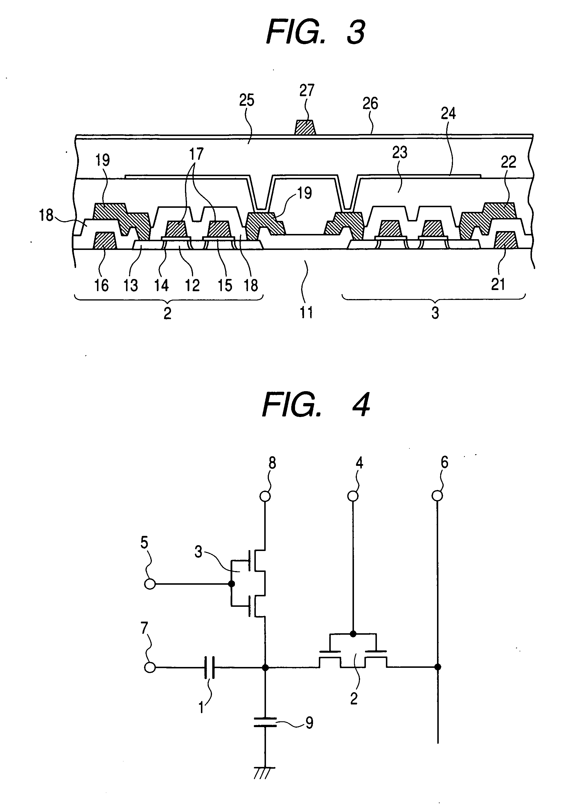
[0052] A radiation image pickup device in which transferring TFT elements and resetting TFT elements are disposed in pixels, respectively, will hereinafter be described as Embodiment 2 of the present invention. Embodiment 2 relates to a direct type radiation image pickup device for directly converting radiation into an electrical signal using a-Se or the like.

[0053] An equivalent circuit diagram of one bit is shown in FIG. 4. The same constituent elements as those of FIG. 1 are designated with the same reference numerals. However, reference numeral 1 designates a radiation conversion element portion. In the figure, the radiation conversion element portion 1 is a direct type radiation conversion element portion for directly converting radiation into an electrical signal. Reference numeral 2 designates a transferring TFT portion; reference numeral 3 designates a resetting TFT portion; reference numeral 4 designates a transferring TFT driving wiring; reference numeral 5, a resetting T...

embodiment 3

[0063] A radiation image pickup device constituted by an AmpTFT (amplifying TFT) having a gate electrode for receiving electric charges generated in a photoelectric conversion element, a transferring TFT for transferring an electrical signal corresponding to these electric charges, and the like will hereinafter be described as Embodiment 3 of the present invention. Embodiment 3 relates to an indirect type radiation image pickup device for wavelength-converting radiation once into light such as visible light to read out the resultant light by photoelectric conversion elements. An MIS type PD or a PIN type PD may also be used for the photoelectric conversion element.

[0064] An equivalent circuit diagram of 1 bit in the photoelectric converter is shown in FIG. 7. In FIG. 7, the same constituent elements as those shown in FIG. 1 are designated with the same reference numerals. In the figure, reference numeral 1 designates a photoelectric conversion element portion; reference numeral 31 ...


PUM


Abstract

In a radiation image pickup device including: a sensor element for converting radiation into an electrical signal; and a thin film transistor connected to the sensor element, an electrode of the sensor element connected to the thin film transistor is disposed above the thin film transistor, and that the thin film transistor has a top gate type structure in which a semiconductor layer, a gate insulating layer, and a gate electrode layer are laminated in this order on a substrate, so that a channel portion of the thin film transistor is protected by a gate electrode, thereby providing stable TFT characteristics without undesirable turning ON any of the TFT elements due to the back gate effect by the fluctuation in electric potentials corresponding to outputs from the sensor electrodes, and thereby greatly improving image quality.

Description

TECHNICAL FIELD [0001] The present invention relates in general to a radiation image pickup device, and more particularly to a substrate for photoelectric conversion and a photoelectric converter, and a substrate for radiation image pickup and a radiation image pickup device, which are applied to a medical image diagnosis system, a non-destructive inspection system, an analyzer using radiation, or the like. Note that, it is supposed that electromagnetic waves such as visible light, and X-rays, alpha rays, beta rays, gamma rays and the like are included in “radiation” used in this specification. In addition, “a wavelength conversion unit” used in this specification means a unit for wavelength-converting radiation, and is supposed to include a phosphor for converting radiation such as X-rays into an optical signal. Moreover, “a semiconductor conversion element” used in this specification means an element for converting at least radiation into electric charges, and for example, is supp...

Claims


Application Information

Patent Timeline
Patent Type & Authority Applications(United States)
IPC IPC(8): H01L31/113H01L27/146H04N5/32
CPCH04N5/32H01L27/14658H01L21/18H01L27/146
Inventor MOCHIZUKI, CHIORIMORISHITA, MASAKAZUWATANABE, MINORUISHII, TAKAMASANOMURA, KEIICHI
Owner CANON KK
Why Eureka
Try Eureka