
Front bumper cover and radiator grille

a radiator grille and front bumper technology, applied in the direction of vehicle bodies, roofs, monocoque constructions, etc., can solve the problems of high proportion of overspray during painting, the addition of joining plates, and the non-uniformity of outer side parts, etc., to achieve a higher occupancy level and high component packing density

Inactive Publication Date: 2006-11-09
DECOMA GERMANY
View PDF5 Cites 44 Cited by
  • Summary
  • Abstract
  • Description
  • Claims
  • Application Information

AI Technical Summary

Benefits of technology

[0009] The construction of the front bumper cover according to the invention enables the radiator grille or mesh to be held satisfactorily in the front bumper cover such that it meets the stringent guidelines regarding the protection of pedestrians.
[0014] In the preferred embodiment, a lower protective bar or lower leg stiffener is provided as an additional connecting member. This lower protective bar located in the region of a sub-frame may thus be used as an additional connecting member between individual cover parts of the front bumper cover. It is important to ensure, among other things, that deformations caused by thermal expansion, for example, are prevented from occurring at the hinged points of attachment to the radiator grille.
[0015] If the front bumper cover is made in several parts, there are considerable cost advantages as smaller injection molding machinery can be used, a higher occupancy level can be achieved on paint shop skids, and a higher packing density of parts in transporting containers is possible. Moreover, inexpensive flat bed paint shops can be used instead of 3-D robot-operated paint shops.
[0017] Construction is also made easier by a reduction in component tolerances caused by the provision of compensating joints. Furthermore, weight can be reduced by eliminating duplicated material.

Problems solved by technology

A disadvantage of the bumper cover described is that the additional joining plate is required.
The non-uniformity of outer side parts of the bumper cover compared with the central radiator grille means that connecting bars are necessary, which are covered by a badge area of the radiator grille.
In addition, there are large openings in the radiator grille which results in a high proportion of overspray during painting and hence high paint consumption.
Moreover, because of their bulky nature fewer one-piece bumper covers can be processed for painting at a time.

Method used


Image

  • Front bumper cover and radiator grille
  • Front bumper cover and radiator grille
  • Front bumper cover and radiator grille

Examples


Embodiment Construction

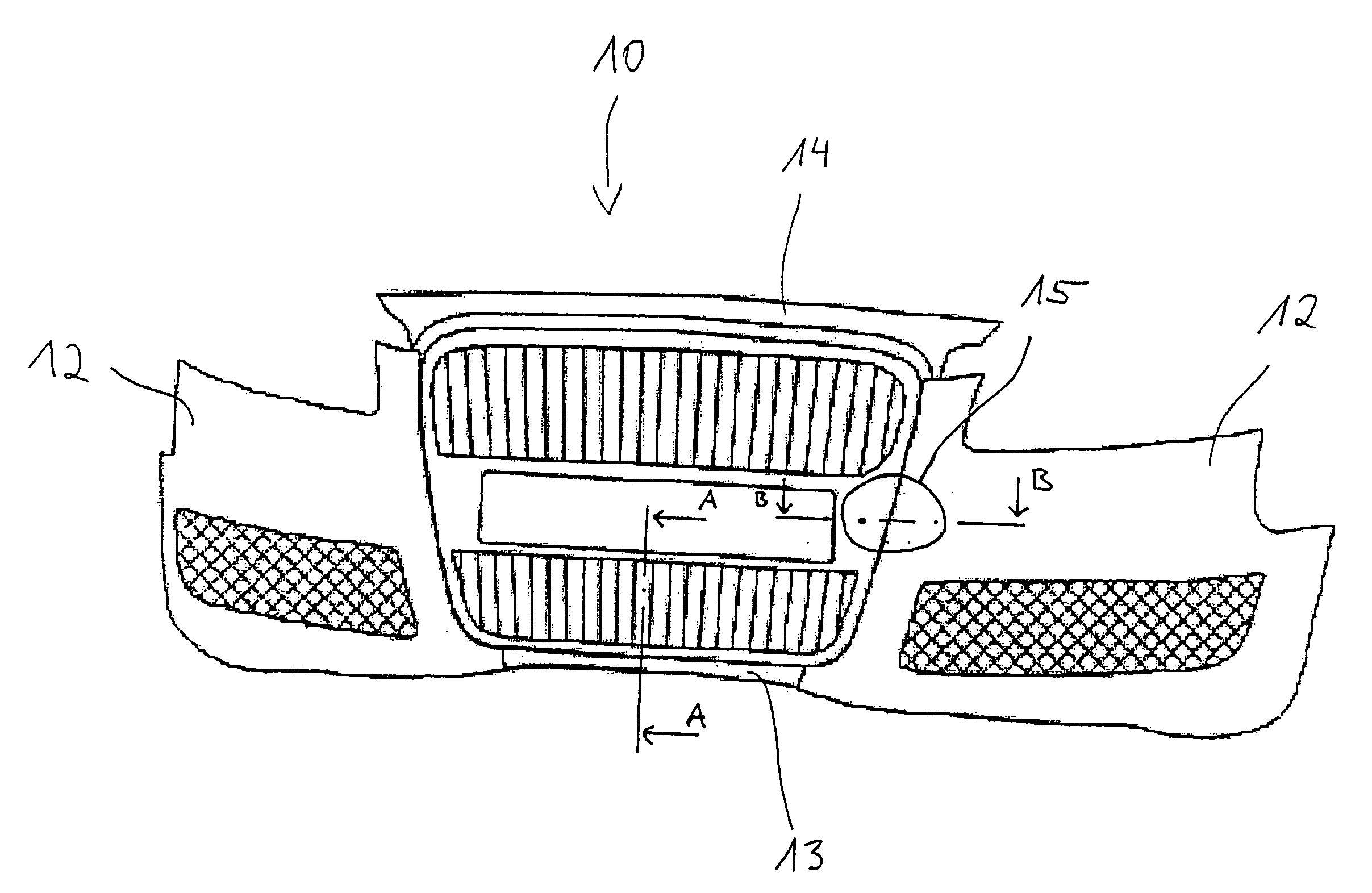
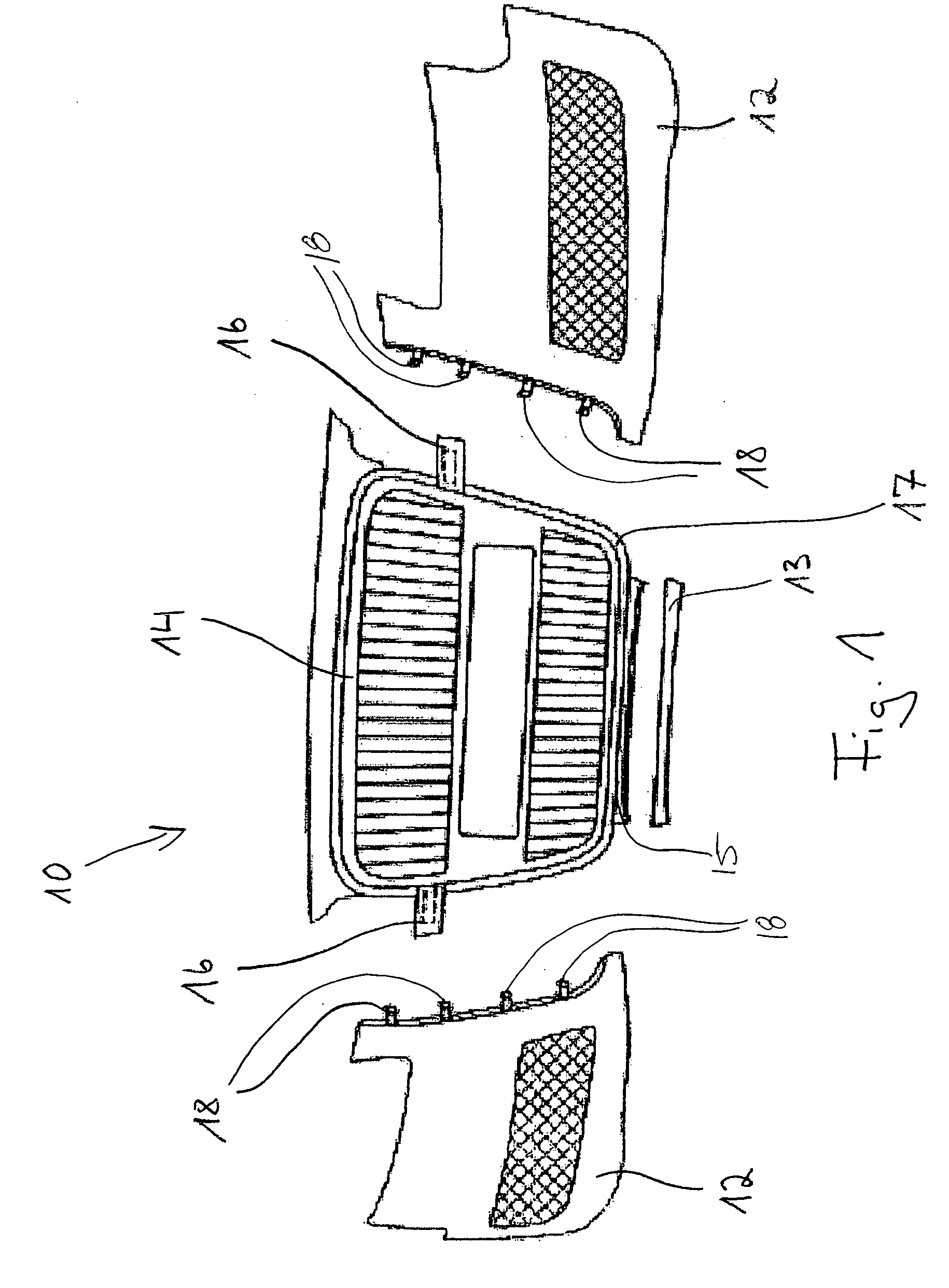
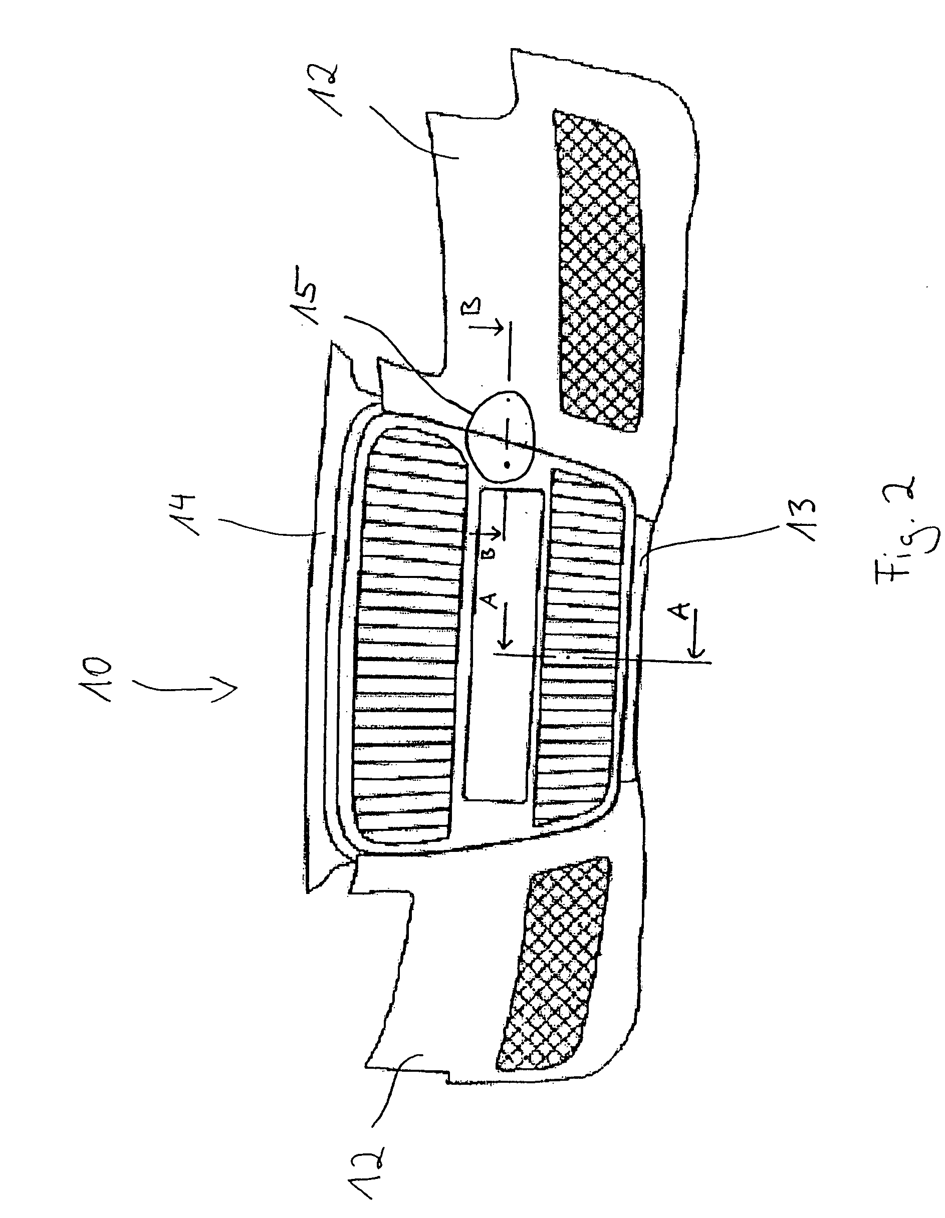
[0029] Referring to FIG. 1, a multi-part front bumper cover is generally shown at 10. In the embodiment shown, the front bumper cover 10 includes two side cover parts 12 and a central cover part 13 which are to be connected to a radiator grille 14. The radiator grille 14 is adapted to mount to an automotive vehicle (not shown) such that the radiator grille 14 acts as a load-bearing element supporting the front bumper cover 10.

[0030] In order to provide for the connection between the side cover parts 12 and the radiator grille 14, the radiator grille 14 includes a bracket-shaped attachment point 16 extending from each side. Additionally, the radiator grille 14 includes a U-shaped profile 17 extending around at least a portion of a peripheral edge thereof, as shown in FIG. 6. The side cover parts 12 include side push-in tabs 18 for fixedly securing the side cover parts 12 to the radiator grille 14. The side push-in tabs 18 may also be latching hooks of various construction 12a, 12b w...


PUM


Abstract

A front bumper cover is provided for an automotive vehicle. The front bumper cover includes a plurality of cover parts and a radiator grille having attachment points for fixedly securing the plurality of cover parts thereto. The radiator grille is adapted to mount to the vehicle thereby acting as a load-bearing element for supporting the front bumper cover.

Description

BACKGROUND OF THE INVENTION [0001] 1. Field of the Invention [0002] The present invention relates to a front bumper cover and, more particularly, to a front bumper cover including a radiator grille. [0003] 2. Description of the Related Art [0004] Bumper covers, which are usually made of plastic, are currently used in virtually all automotive vehicles. The bumper covers are usually one-piece or, if made of several pieces, are divided approximately along a horizontal plane and are reinforced, if necessary, by means of additional components at the edge areas bordering on adjacent parts. These reinforcing parts are either foam parts made of expanded polypropylene or polyurethane, injection molded components, or metal parts which are attached to the cover by various means, such as by clipping, welding, adhesive bonding, screwing, or clamping. [0005] German Patent DE 195 46 478 A1 discloses a bumper cover made of plastic which consists of at least two individual parts joined together alon...

Claims


Application Information

Patent Timeline
IPC IPC(8): B60R19/52
CPCB60R19/04B60R19/52B60R2019/527B60R2019/1886B60R21/34
Inventor FLOTZINGER, FRANZ
Owner DECOMA GERMANY
Learn More