Layer-built capacitor, and its manufacturing method

a multi-layer capacitor and manufacturing method technology, applied in the direction of variable capacitors, fixed capacitors, fixed capacitor details, etc., can solve the problems of inability to produce the required noise absorption characteristics, inability to sufficiently reduce the noise in such a frequency band, and inability to stably operate multi-layer ceramic capacitors in a higher frequency band. , to achieve the effect of improving the reliability of connection, reducing the esl, and easy increasing the esr

Active Publication Date: 2006-11-09
MURATA MFG CO LTD
View PDF4 Cites 33 Cited by
  • Summary
  • Abstract
  • Description
  • Claims
  • Application Information

AI Technical Summary

Benefits of technology

[0040] Consequently, the multilayer capacitor according to the preferred embodiments described above contributes to providing flat impedance characteristics and can be advantageously used as a decoupling capacitor for noise absorption and for smoothing a variation in the power supply in, for example, an MPU.
[0041] Further providing the dummy electrode so as to be layered on the terminal connecting portion of the internal electrode with a dielectric layer disposed therebetween can improve the reliability of the connection between the internal electrode and the external terminal electrode.
[0042] Making the extended portion curved in the direction of its thickness narrower than the capacitance generating portion and the terminal connecting portion or making the extended portion curved in the direction of its thickness thinner than the capacitance generating portion and the terminal connecting portion can easily increase the ESR.
[0043] Providing at least one pair of the internal electrodes near the main surface of the main body, opposing the mounting surface, decreases a minimum current loop provided between the first and second external terminal electrodes so as to contribute to decreasing ...

Problems solved by technology

When, for example, a multilayer ceramic capacitor is used, such as the decoupling capacitor described above, there is a problem in that it is difficult for the multilayer ceramic capacitor to stably operate in a higher frequency band because the multilayer ceramic capacitor is characterized by having a capacitance variation of several percent and specific temperature characteristics.
As a result, there is a problem in that it is not possible to sufficiently reduce the noise in such a frequency band.
However, if the resistance of the resistor connected in series is too high, the valleys rise, that is, the impedance increases while flat impedance characteristics can be produced and, therefore, it is not possible to produce the required n...

Method used


Image

  • Layer-built capacitor, and its manufacturing method
  • Layer-built capacitor, and its manufacturing method
  • Layer-built capacitor, and its manufacturing method

Examples


Embodiment Construction

[0063] Preferred embodiments of a multi-terminal capacitor will now be described.

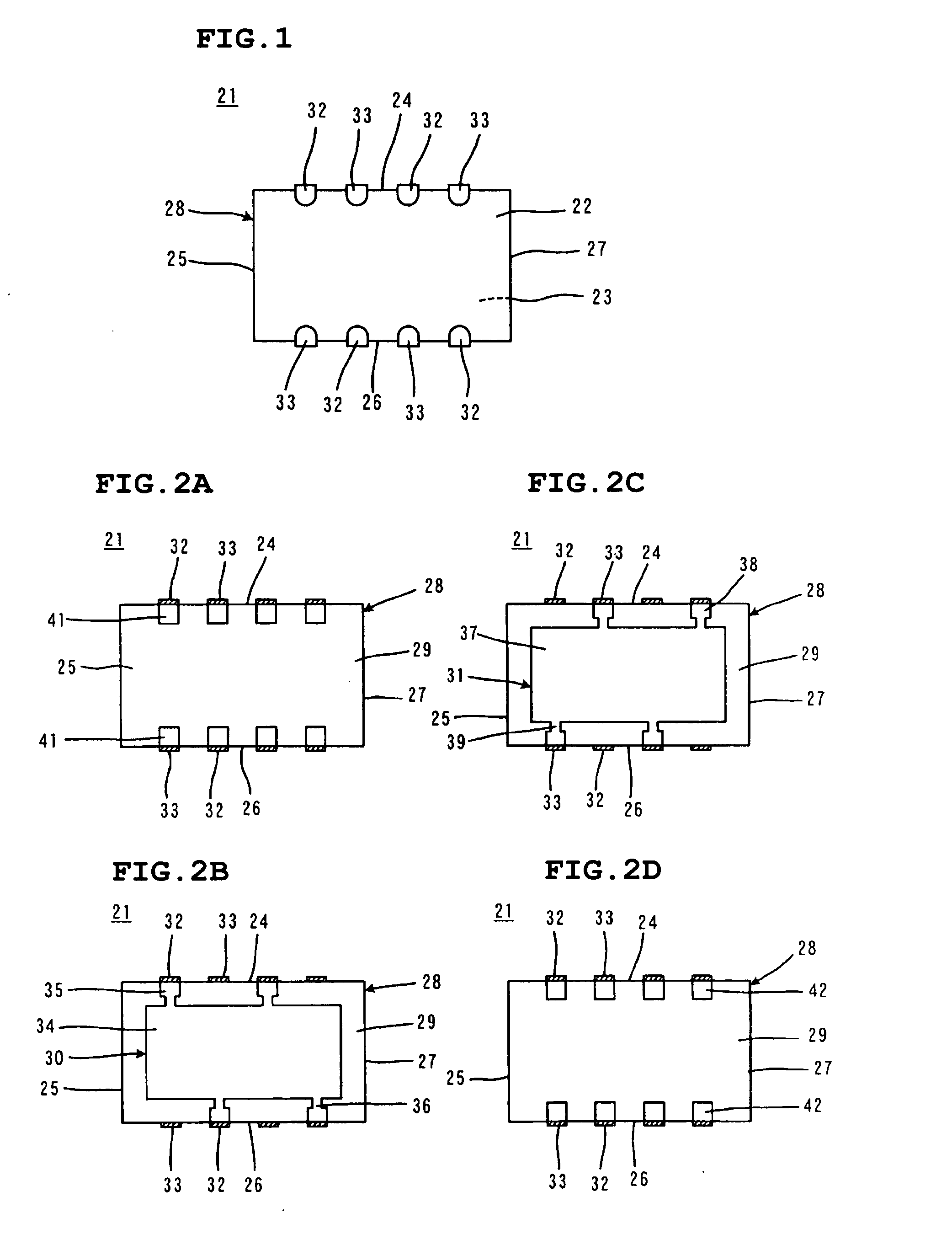
[0064] A first preferred embodiment of the present invention will be described with reference to FIGS. 1 to 5. FIG. 1 is an external view of a multi-terminal capacitor 21. FIGS. 2A to 2D include plan views showing the internal structure of the multi-terminal capacitor 21, and showing different cross sections of the multi-terminal capacitor 21.

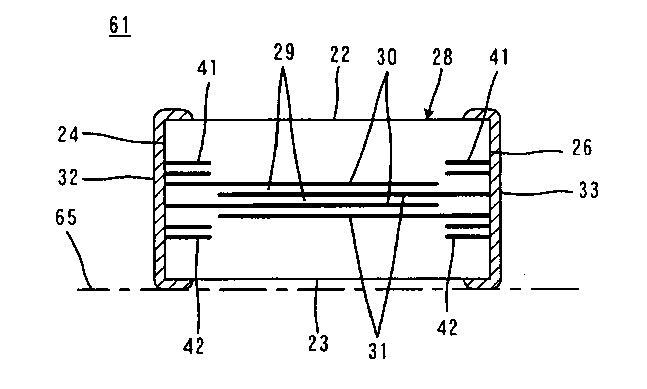
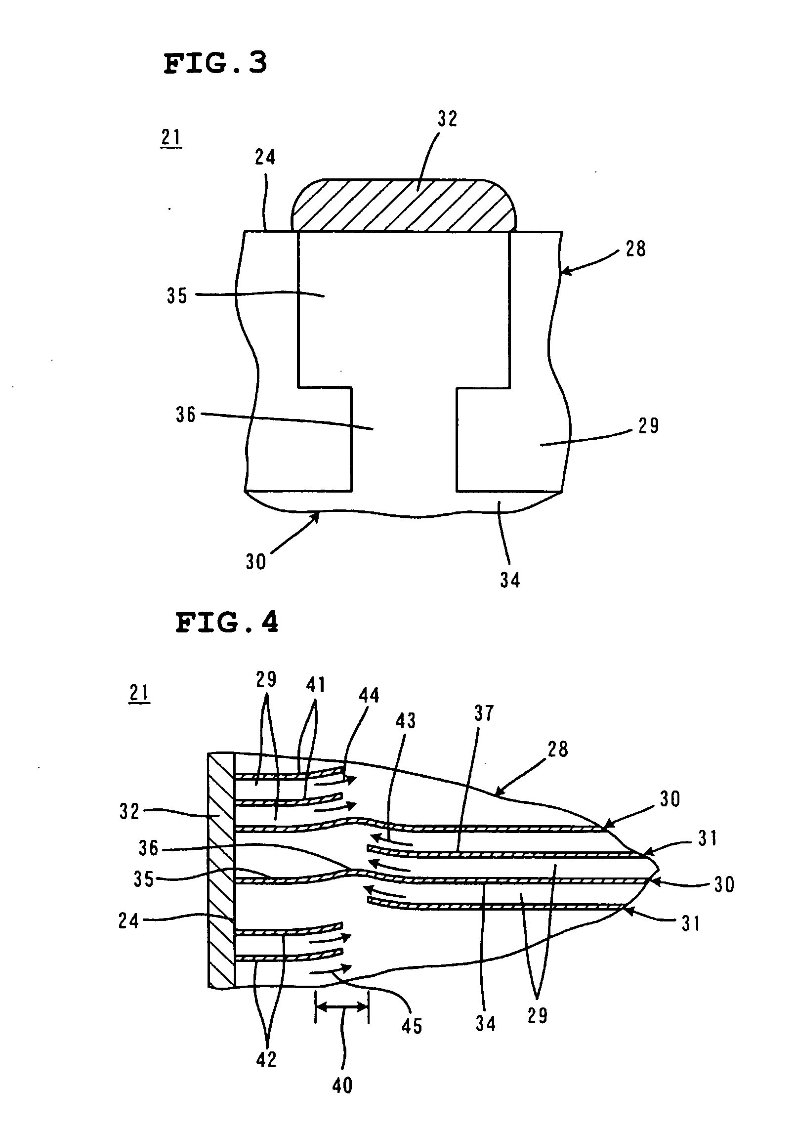
[0065] The multi-terminal capacitor 21 preferably has a substantially rectangular prismatic main body 28 including two main surfaces 22 and 23 opposed to each other and four side surfaces 24, 25, 26, and 27 connecting the main surface 22 to the main surface 23, as shown in the external view in FIG. 1.

[0066] The main body 28 has a layered structure and includes a plurality of dielectric layers 29 that extend in the direction in which the main surfaces 22 and 23 extend and are layered on top of one another, and at least one pair of first and second internal electr...


PUM

PropertyMeasurementUnit
Thicknessaaaaaaaaaa
Capacitanceaaaaaaaaaa

Abstract

A multilayer capacitor includes first and second internal electrodes that are opposed to each other so as to generate an electrostatic capacitance and have a capacitance generating portion functioning to generate the electrostatic capacitance, terminal connecting portions connected to corresponding external terminal electrodes, and extended portions connecting the capacitance generating portion to the terminal connecting portions. The extended portions are narrower than the capacitance generating portion and the terminal connecting portion and are curved in the direction of their thickness so as to provide a longer effective length. The multi-terminal capacitor is capable of increasing an ESR without adding a separate additional element.

Description

BACKGROUND OF THE INVENTION [0001] 1. Field of the Invention [0002] The present invention relates to a multilayer capacitor and a method of manufacturing the multilayer capacitor. More particularly, the present invention relates to an improvement in the structure of an internal electrode in the multilayer capacitor. [0003] 2. Description of the Related Art [0004] An equivalent circuit of a capacitor is represented by a circuit having C, L, and R connected in series, where the capacitance of the capacitor is denoted by C, an equivalent series inductance (ESL) is denoted by L, and an equivalent series resistance (ESR) is denoted by R. [0005] The resonant frequency (f0) of this equivalent circuit is equal to 1 / [2π×(L×C)1 / 2] and the equivalent circuit does not function as a capacitor in a frequency band higher than this resonant frequency. In other words, decreasing the value of L, or ESL, increases the resonant frequency and, therefore, the equivalent circuit functions as a capacitor i...

Claims


Application Information

Patent Timeline
IPC IPC(8): H01G4/255H01G4/232H01G4/12H01G4/30
CPCH01G4/12Y10T29/435H01G4/30H01G4/232
Inventor TAKASHIMA, HIROKAZUTAKAGI, YOSHIKAZUUEOKA, HIROSHIYOSHIDA, TERUO
Owner MURATA MFG CO LTD
Why Eureka
Try Eureka