
Radio resource allocation in telecommunication system

Inactive Publication Date: 2006-11-09
NOKIA CORP
View PDF5 Cites 30 Cited by
  • Summary
  • Abstract
  • Description
  • Claims
  • Application Information

AI Technical Summary

Benefits of technology

[0016] The invention provides several advantages. The invention provides improved control of multiple access interference through effective radio resource allocation in a cellular telecommunication system. As a result, data throughput of the cellular telecommunication system is increased. The invention also provides improved mitigation of the near-far effect through effective radio resource allocation in the cellular telecommunication system. Additionally, the invention may be used in the cells of the cellular telecommunication system independently without any coordination between the cells.

Problems solved by technology

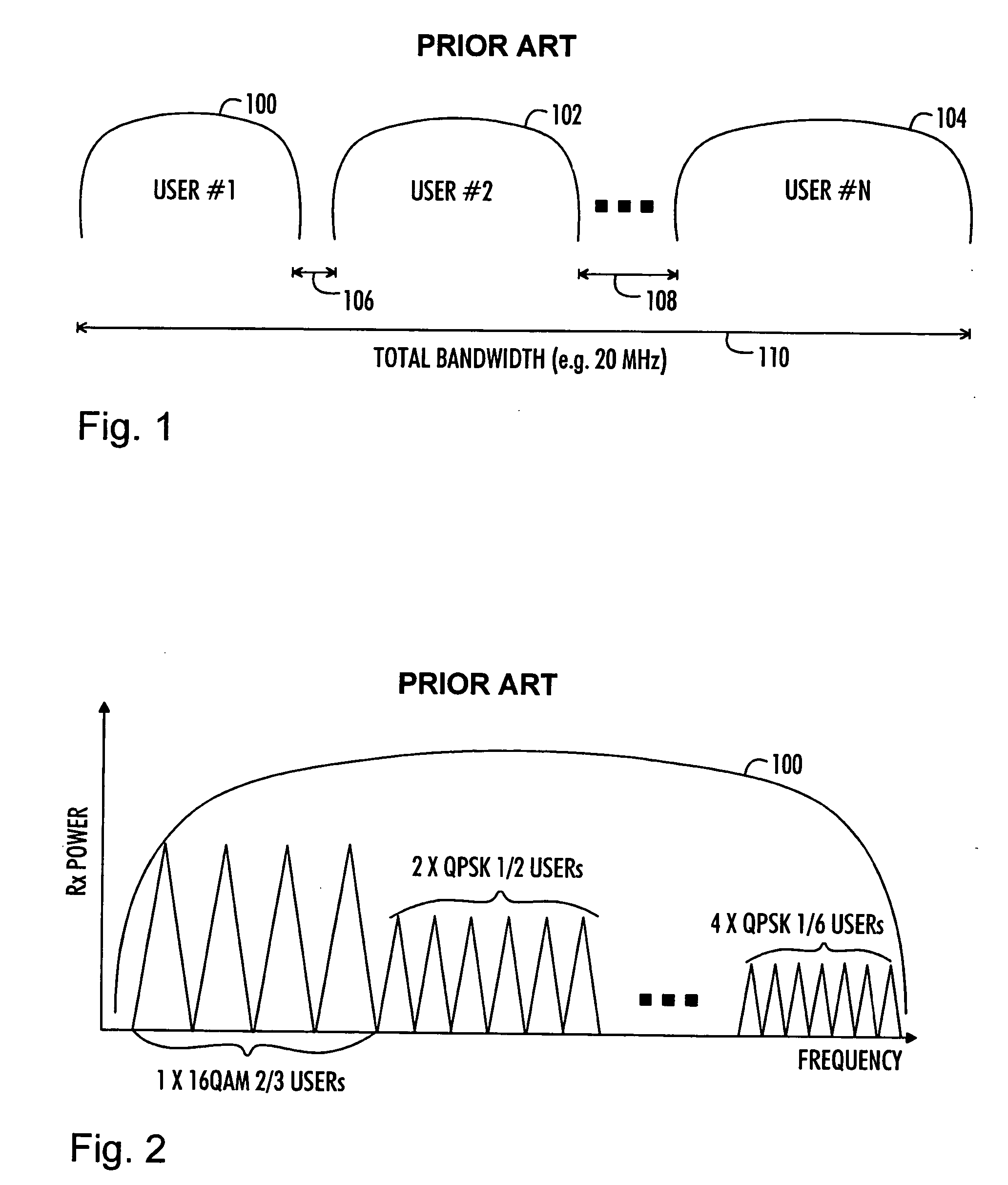
The performance of the uplink of FDMA and OFDMA is sensitive to non-idealities, such as a frequency error and phase noise.
Generally, the frequency error is caused by Doppler shift and frequency synchronization errors between uplink and downlink transceivers.
The problem related to the frequency error is severe in the uplink direction where each terminal has its own local oscillator synchronized with the base station's local oscillator in a downlink direction.
The non-idealities produce adjacent channel leakage.
This, in turn, causes multiple access interference, which means that different users of the FDMA / OFDMA system start to interfere each other at the base station receiver.
The higher the power differences between the received levels of different users using the adjacent bands, the greater the problem with multiple access interference.
The drawback of SC-FDMA is that rather broad guard bands and long guard times are needed, which causes a high overhead.
This, in turn, will decrease the spectrum efficiency of the system.
The problem is greatest with the narrowest transmission bandwidths.
The problem with this approach is that the users having high received power levels (e.g. 16 QAM, effective code rate (ECR)=⅔) cause strong interference to other users having low received power levels.
The interference problem is more severe if there are frequency errors in the system.

Method used


Image

  • Radio resource allocation in telecommunication system
  • Radio resource allocation in telecommunication system
  • Radio resource allocation in telecommunication system

Examples


Embodiment Construction

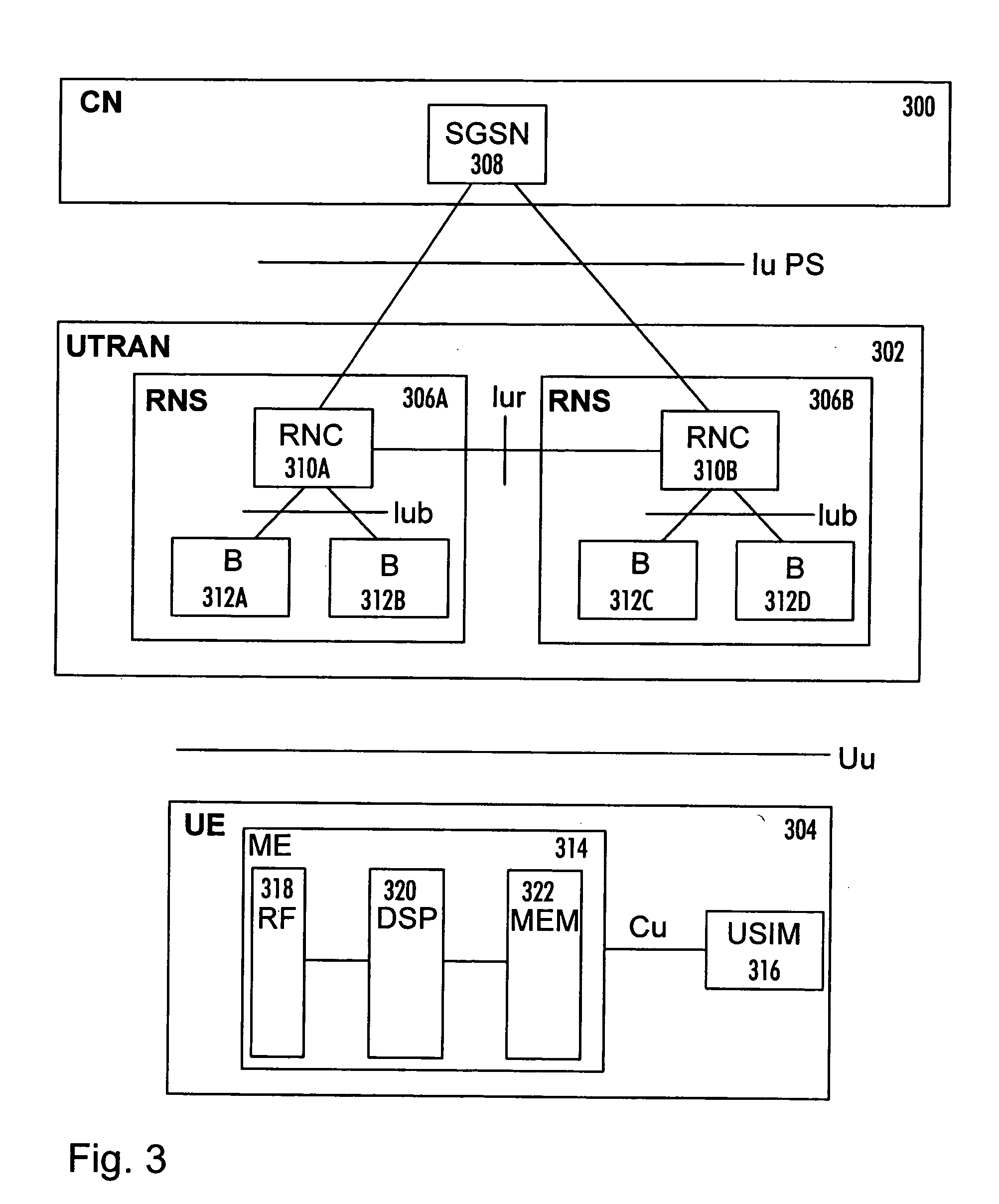
[0026]FIG. 3 illustrates an example of a wireless cellular telecommunications system to which the present solution may be applied. Below, embodiments of the invention will be described using the UMTS (Universal Mobile Telecommunications System) as an example of the cellular telecommunications system. The invention may, however, be applied to other cellular telecommunication systems. The structure and functions of such a cellular telecommunications system and those of the associated network elements are only described when relevant to the invention.

[0027] The cellular telecommunications system may be divided into a core network (CN) 300, a UMTS terrestrial radio access network (UTRAN) 302, and a user terminal (UE) 304. The core network 300 and the UTRAN 302 compose a network infrastructure of the wireless telecommunications system.

[0028] The UTRAN 302 is typically implemented with wideband code division multiple access (WCDMA) radio access technology.

[0029] The core network 300 in...


PUM


Abstract

A solution for radio resource allocation in a cellular telecommunication system is provided. According to the invention, the frequency bands of a plurality of cells of the telecommunication system are divided independently into more than one frequency band sub-block. User terminals within the coverage area of each cell are then allocated to the frequency band sub-blocks on the basis of the modulation and coding schemes used by the user terminals. Furthermore, transmission power of the user terminals is controlled on the basis of the allocation of the user terminals in order to improve data throughput.

Description

FIELD [0001] The invention relates to radio resource allocation in a cellular telecommunication system. BACKGROUND [0002] Frequency Division Multiple Access (FDMA) technology is widely used in wireless communication systems. FDMA refers to a wireless communication technique in which a frequency spectrum is divided into a plurality of smaller frequency components. Each component of the spectrum has a carrier signal that can be modulated with data. This increases the amount of data that can be communicated over the spectrum, and also provides a mechanism for allocating a bandwidth to service providers. [0003] For example, in the upcoming evolution of 3GPP (3rd Generation Partnership Project) systems, FDMA offers a promising technology for increasing the throughput performance of a 3.9G uplink (UL). In an isolated cell, the gain of FDMA over WCDMA is evident. In non-isolated cells, the gain is slightly smaller and depends mainly on the required coverage area probability. An FDMA Uplink...

Claims


Application Information

Patent Timeline
IPC IPC(8): H04J1/00H04BH04L5/02H04L5/06H04W28/04H04W52/24H04W52/34H04W72/00H04W72/04
CPCH04L5/023H04L5/06H04W28/04H04W52/241H04W72/0453H04W52/245H04W52/346H04W72/00H04W52/242H04W72/20
Inventor PAJUKOSKI, KARITIIROLA, ESAHORNEMAN, KARI
Owner NOKIA CORP
Learn More