Network system

a network system and network technology, applied in the field of network systems, can solve the problems of affecting network efficiency, plurality of limitations that affect network efficiencies, and difficulty in achieving the affinity between stateful sessions, so as to reduce dma latency, reduce processing penalties, and increase dma bandwidth

Active Publication Date: 2006-11-09
ORACLE INT CORP
View PDF41 Cites 152 Cited by
  • Summary
  • Abstract
  • Description
  • Claims
  • Application Information

AI Technical Summary

Benefits of technology

[0011] In accordance with the present invention, a network interface unit is set forth which enables an unconstrained number of queues between a network interface and its system, which coordinates the servicing of shared queues, which provides for affinity between stateful sessions and processors over time, which coordinates interrupt driven packet arrival notification, which lowers DMA latency and increases DMA bandwidth to approximate memory accesses, which takes into account multiple packet memory representations and which coordinates asynchronous interrupt notifications to minimize processing penalties associated with taking an interrupt.

Problems solved by technology

Scalability underlies many of the limitations of known I / O architectures.
On one hand, there is the desirability of being able to augment the capabilities of an existing system over time by adding additional computational resources so that systems always have reasonable room to grow.
There are a plurality of limitations that affect network efficiencies.
Also for example, the number of processors servicing a network interface is constrained by the processor having to coordinate service of shared queues, when using multiple processors; it is difficult to achieve a desired affinity between stateful sessions and processors over time.
Also for example, multiple packet memory representations are simultaneously used at different levels of a packet processing sequence with consequent overhead of transforming representations.
Also for example, asynchronous interrupt notifications incur a processing penalty of taking an interrupt.
The processing penalty can be disproportionately large considering a worst case interrupt rate.

Method used


Image

  • Network system
  • Network system
  • Network system

Examples


Embodiment Construction

[0047] Network System Overview

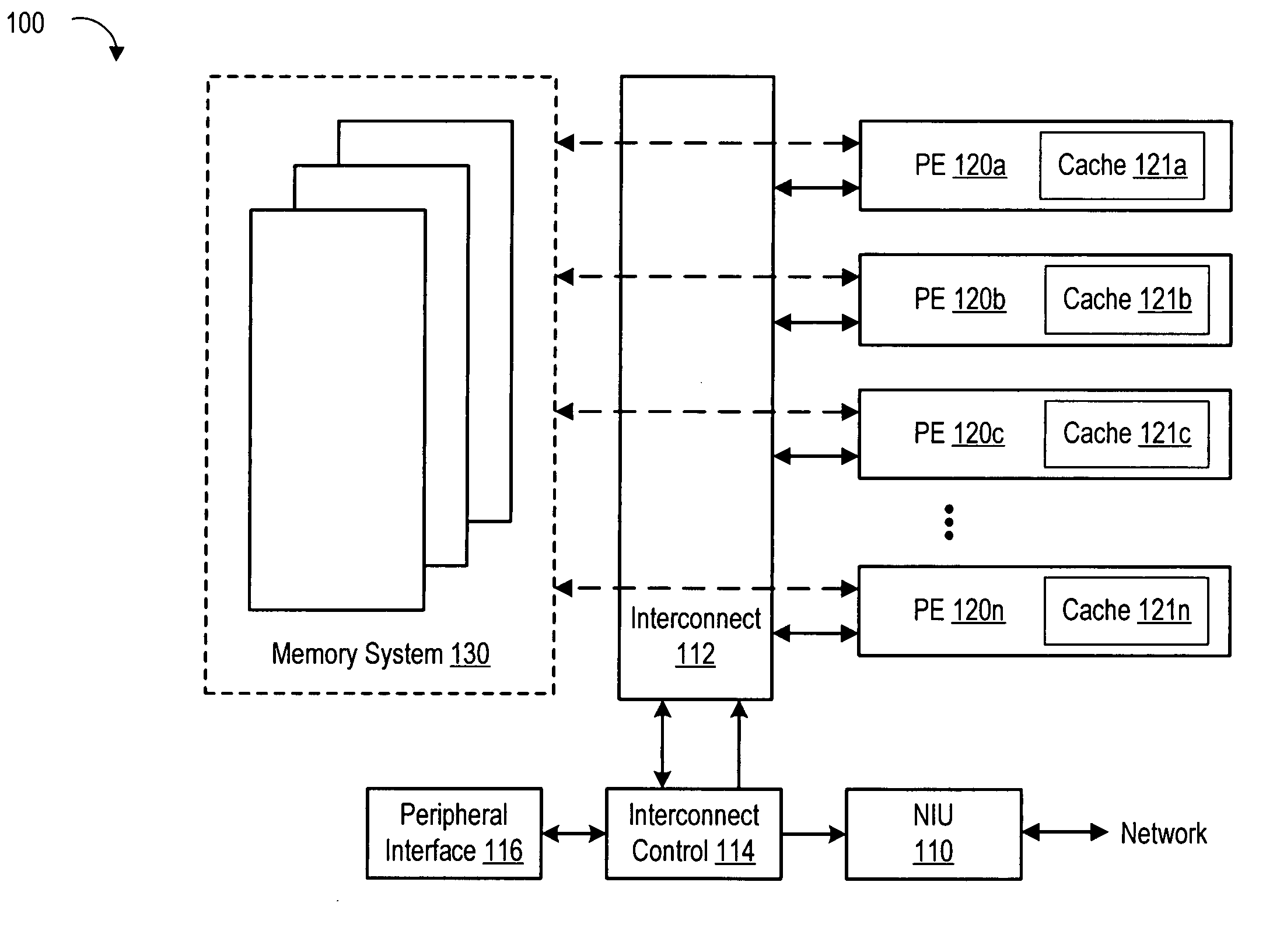
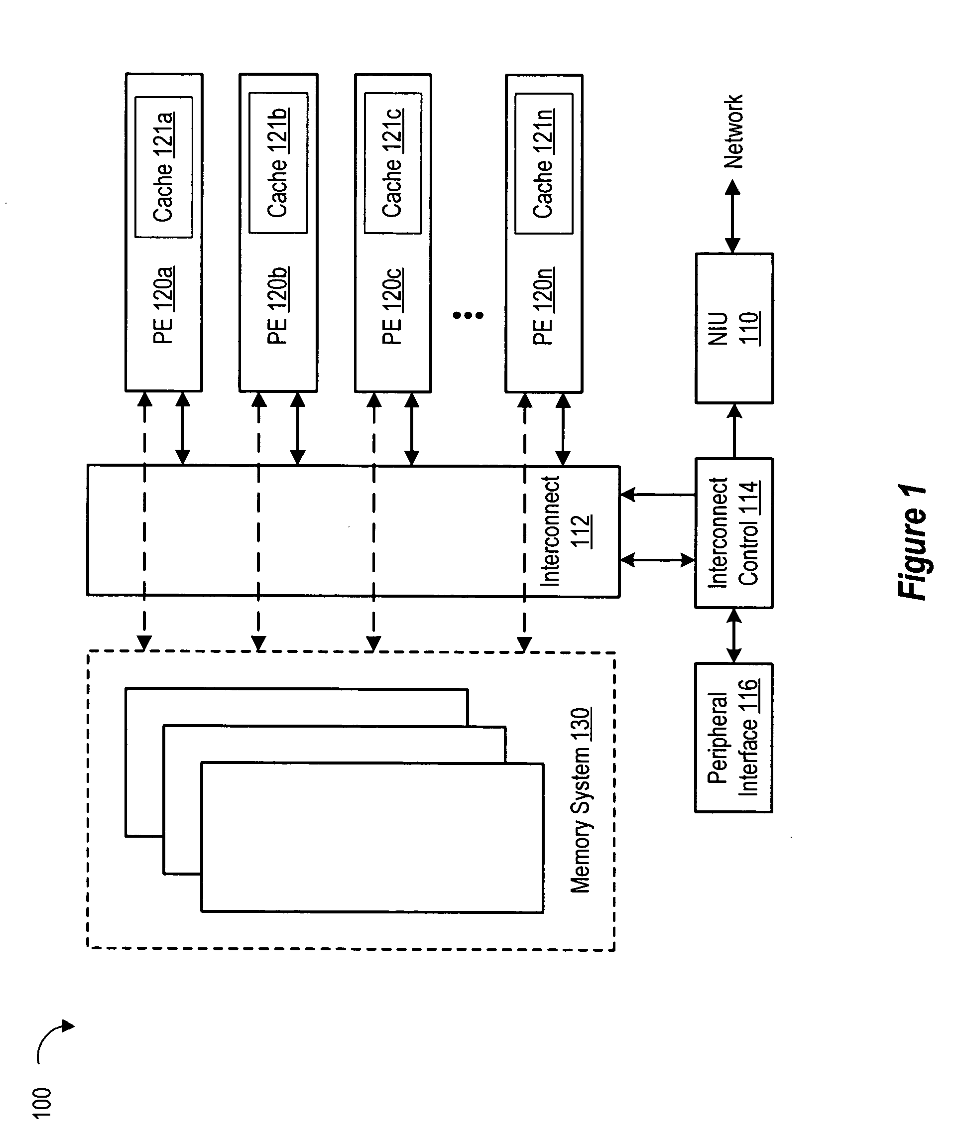
[0048] Referring to FIG. 1, a block diagram of a network system 100 is shown. More specifically, the network system 100 includes a network interface unit 110 which is coupled to an interconnect device 112 via an interconnect controller 114. The interconnect controller 114 is also coupled to a peripheral interface module 116. The interconnect device 112 is also coupled to a plurality of processing entities 120 and to memory system 130. The processing entities 120 are coupled to the memory system 130. Each processing entity 120 includes a respective cache 121.

[0049] The interconnect device 112 may be an input / output (I / O) bus (such as e.g., a PCI Express bus) along with a corresponding bus bridge, a crossbar switch or any other type of interconnect device. In one embodiment, the interconnect device 112 or a bus bridge within the interconnect device 112 may include an I / O memory management unit (IOMMU). The interconnect device 112 may be conceptualized a...


PUM


Abstract

A network system which includes a plurality of processing entities, an interconnect device coupled to the plurality of processing entities, a memory system coupled to the interconnect device and the plurality of processing entities, a network interface unit coupled to the plurality of processing entities and the memory system via the interconnect device. The network interface includes a memory access module and a packet classifier. The memory access module includes a plurality of parallel memory access channels. The packet classifier provides a flexible association between packets and the plurality of processing entities via the plurality of memory access channels.

Description

BACKGROUND OF THE INVENTION [0001] 1. Field of the Invention [0002] The present invention relates to networking and more particularly to network systems. [0003] 2. Description of the Related Art [0004] In known networked computer systems, the network interface functionality is treated and supported as an undifferentiated instance of a general purpose Input Output (I / O) interface. This treatment is because computer systems are optimized for computational functions, and thus networking specific optimizations that might not apply to generic I / O scenarios. A generic I / O treatment results in no special provisions being made to favor network workload idiosyncrasies. Known networked computer systems include platform servers, server based appliances and desktop computer systems. [0005] Known specialized networking systems, such as switches, routers, remote access network interface units and perimeter security network interface units include internal architectures to support their respective...

Claims


Application Information

Patent Timeline
Patent Type & Authority Applications(United States)
IPC IPC(8): H04L12/66
CPCH04L45/745H04L47/10H04L47/2441H04L47/283H04L49/9063H04L47/326H04L49/90H04L49/901H04L49/9031H04L47/30
Inventor MULLER, SHIMONHENDEL, ARIELGAJJAR, YATINWONG, MICHAELPURI, RAHOULLIN, MAY
Owner ORACLE INT CORP
Why Eureka
Try Eureka