Peelable photoresist for carbon nanotube cathode

a carbon nanotube and cathode technology, applied in the field of photolithography, can solve the problems of limited alignment tolerance of pixels, limited mask alignment tolerance, and constraint pixel resolution, so as to achieve higher pixel resolution of photolithography, eliminate any associated contamination effects, and accurate alignment

Inactive Publication Date: 2006-11-09
APPLIED NANOTECH HLDG
View PDF6 Cites 19 Cited by
  • Summary
  • Abstract
  • Description
  • Claims
  • Application Information

AI Technical Summary

Benefits of technology

[0008] The merits of the present invention over the prior art for defining pixel area are manifold. A peelable photoresist provides the more accurate alignment and higher pixel resolution of photolithography as opposed to using shadow masks. A peelable photoresist eliminates the need for a shadow mask and thus eliminates any associated contamination effects of CNT ink becoming deposited in undesirable areas of the device, as can occur using shadow masks. A peelable photoresist eliminates the need for wet processes during photolithography mask removal, and thus preserves high CNT emitter performance of the pixel cathode. Additionally, a peelable photoresist may be used to avoid wet stripping in other applications, such as manufacturing of integrated circuits, where standard photolithography processes are used.

Problems solved by technology

Each of these two methods has a unique drawback associated with it.
Using the shadow mask method, the alignment tolerance of the pixels is limited by the mechanical accuracy of positioning the shadow mask.
This mask alignment limitation constrains the pixel resolution.
Also, there is a gap between the substrate and the shadow mask that causes CNT ink or solution to leak through the mask edge.
This contamination by conductive CNT ink 105 in undesirable areas of the device increases the likelihood of short circuits when the contact grid structure for the pixels is subsequently applied during manufacture of the display.
The shadow mask method is therefore not suitable for industrial applications involving high volume manufacturing subject to rigorous quality standards.
Using a standard photolithography process, involving a photoresist coating and wet stripping of the resist, CNT material becomes exposed to a chemical solution and water, which adversely affects the CNT emitter performance.

Method used


Image

  • Peelable photoresist for carbon nanotube cathode
  • Peelable photoresist for carbon nanotube cathode
  • Peelable photoresist for carbon nanotube cathode

Examples


Embodiment Construction

[0022] In the following description, numerous specific details are set forth such as specific substrate materials to provide a thorough understanding of the present invention. However, it will be obvious to those skilled in the art that the present invention may be practiced without such specific details. In other instances, well-known circuits have been shown in block diagram form in order not to obscure the present invention in unnecessary detail. For the most part, details concerning timing considerations and the like have been omitted inasmuch as such details are not necessary to obtain a complete understanding of the present invention and are within the skills of persons of ordinary skill in the relevant art.

[0023] Refer now to the drawings wherein depicted elements are not necessarily shown to scale and wherein like or similar elements are designated by the same reference numeral through the several views.

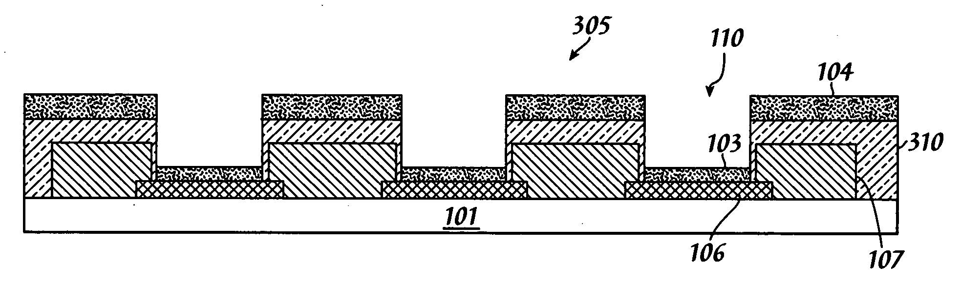
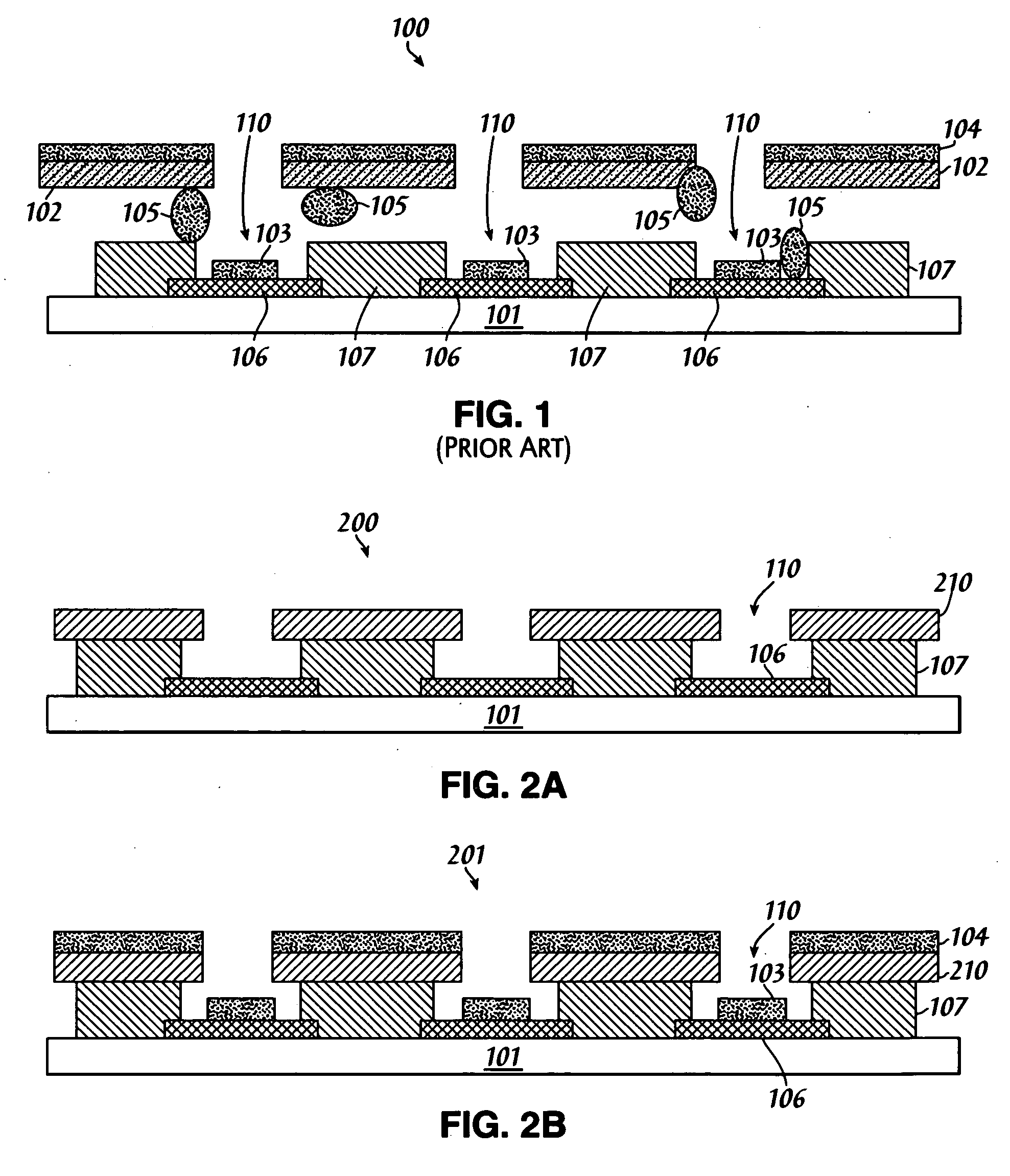
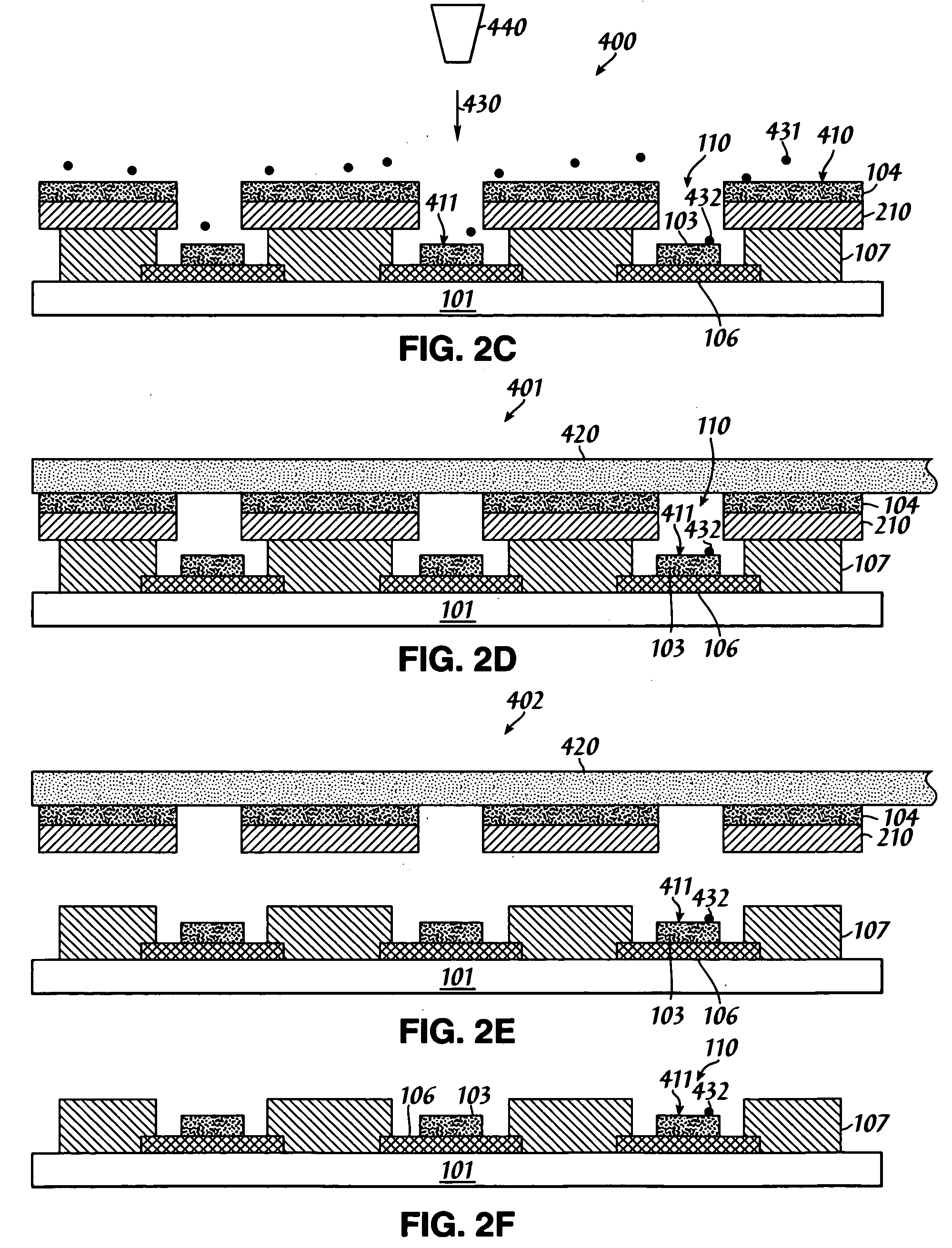
[0024] The present invention provides a method of using a peelable pho...


PUM

PropertyMeasurementUnit
conductingaaaaaaaaaa
insulatingaaaaaaaaaa
threshold voltageaaaaaaaaaa

Abstract

A method for forming a field emission cathode device is disclosed using a peelable photoresist with standard photolithography processes for patterning a deposition mask, except that the peelable photoresist can be peeled away in dry form. The method offers standard photoresist accuracy with the advantage of high patterning resolution for producing carbon nanotube (CNT) field emitter displays. Example methods using a single peelable photoresist layer, and using two distinct layers of photoresist and peelable film, are presented. Since the method does not require wet processes after CNT deposition, it ensures enhanced CNT emitter performance. In addition, an activation process that liberates CNTs can be performed just before a tape lamination and peeling process step. In this manner, all superfluous nanoparticle material remains confined between the tape and photoresist films, which are removed together and properly discarded.

Description

[0001] The present application is a continuation-in-part of U.S. patent application Ser. No. 11 / 124,332, and is also a continuation-in-part of U.S. patent application Ser. No. 10 / 269,577, which claims priority to provisional patent applications: 60 / 343,642; 60 / 348,856; and 60 / 369,794.TECHNICAL FIELD [0002] The present invention relates in general to photolithography, and in particular to applying a peelable photoresist to manufacture carbon nanotube (CNT) cathodes. BACKGROUND INFORMATION [0003] Carbon nanotube (CNT) cathode structures are highly effective field emitters for generating cathode rays, exhibiting a high emission current at a low threshold voltage. CNT cathodes can be fabricated, using procedures known for manufacturing semiconductors, as a plurality of microcells to generate an array of pixels, which form the basis for a display device, such as a television, or a computer monitor. Fabrication of CNT cathodes into an array of pixels typically requires masks to align the ...

Claims


Application Information

Patent Timeline
Patent Type & Authority Applications(United States)
IPC IPC(8): H01L21/00C01BC01B31/02H01J1/00H01J1/02H01J9/02H01J9/24H01L51/40
CPCB82Y10/00B82Y30/00B82Y40/00H01J2201/30469H01J9/025H01J31/127C01B31/0206C01B32/15
Inventor YANIV, ZVIYANG, MOHSHIMAO, DONGSHENG
Owner APPLIED NANOTECH HLDG
Why Eureka
Try Eureka