
Aerodynamic truck trailer airflow control device

a technology for airflow control and truck trailers, which is applied in vehicle heating/cooling devices, vehicle components, vehicle body streamlining, etc. it can solve the problems of air impinging on rotating tires, increasing spray and splash, and rotating tires spraying and splashing in a manner that is worse than, so as to reduce spray and splash, increase spray and splash control, and reduce aerodynamic drag

Inactive Publication Date: 2006-11-09
AIRMAN
View PDF19 Cites 32 Cited by
  • Summary
  • Abstract
  • Description
  • Claims
  • Application Information

AI Technical Summary

Benefits of technology

[0007] An airflow control device constructed according to the principles of the present invention preferably uses air in a way that draws the air down to the highway surface and toward a centerline of the vehicle, thus substantially reducing splash and spray.
[0008] According to one embodiment of the present invention, an improved undermounted airflow control device may comprise a plurality of panels assembled together in a manner that permits them to collect and direct impinging air to exit between the trailer tires and beneath the axles. Using the airflow control device, the large volume of air collected and forced between the tires and beneath the axles increases in velocity as it exits, thereby producing a low-pressure area that further helps eliminate or substantially reduce splash and spray as the surrounding air is drawn into the low pressure area.
[0009] The airflow control device can be mounted rigidly or slidably to the underside of a trailer, preferably ahead of the rearmost trailer tire assembly to collect the incoming air. In a preferred embodiment, the incoming air preferably impinges on a panel or other means for deflecting air that extends all the way across from one outboard side of the trailer to the other, and that further preferably extends from the underside of the trailer down to approximately a lower portion of the trailer tire axles. The forward collection panel or panels are preferably sloped to decrease the parasitical drag on the trailer tire / axle assembly. The sloped panel or panels are further preferably angled sufficiently to direct all or a majority of the impinging air downwards towards the ground. The device may further have one or more panel sections arranged in a horizontal orientation to allow compression and columniation of the air and to direct it between the tires and under the axles.

Problems solved by technology

This causes the air to impinge upon the rotating tires and increases spray and splash.
The water entrained air causes the rotating tires to spray and splash in a manner that is worse than without the unit.

Method used


Image

  • Aerodynamic truck trailer airflow control device
  • Aerodynamic truck trailer airflow control device
  • Aerodynamic truck trailer airflow control device

Examples


Embodiment Construction

[0023] The principles of the present invention will now be described more fully hereinafter with reference to various exemplary embodiments thereof. It should be recognized, however, that the invention may be embodied in many different forms and should therefore not be construed as being limited to any one or more of the embodiments set forth herein.

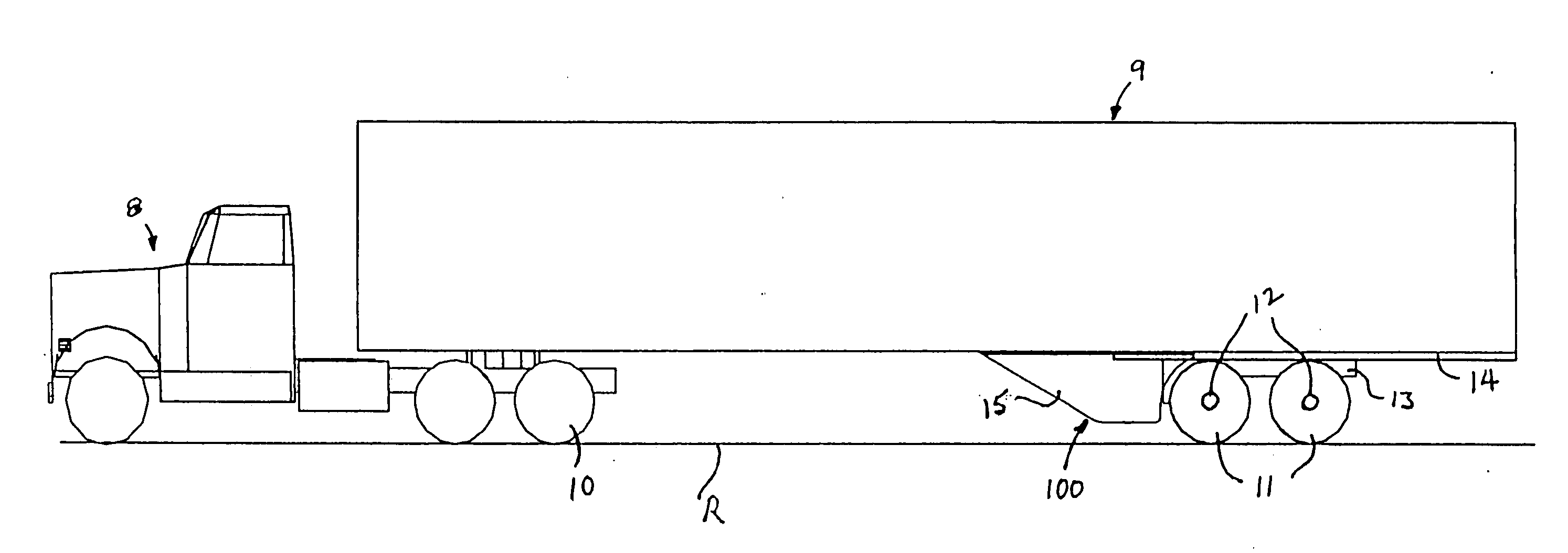
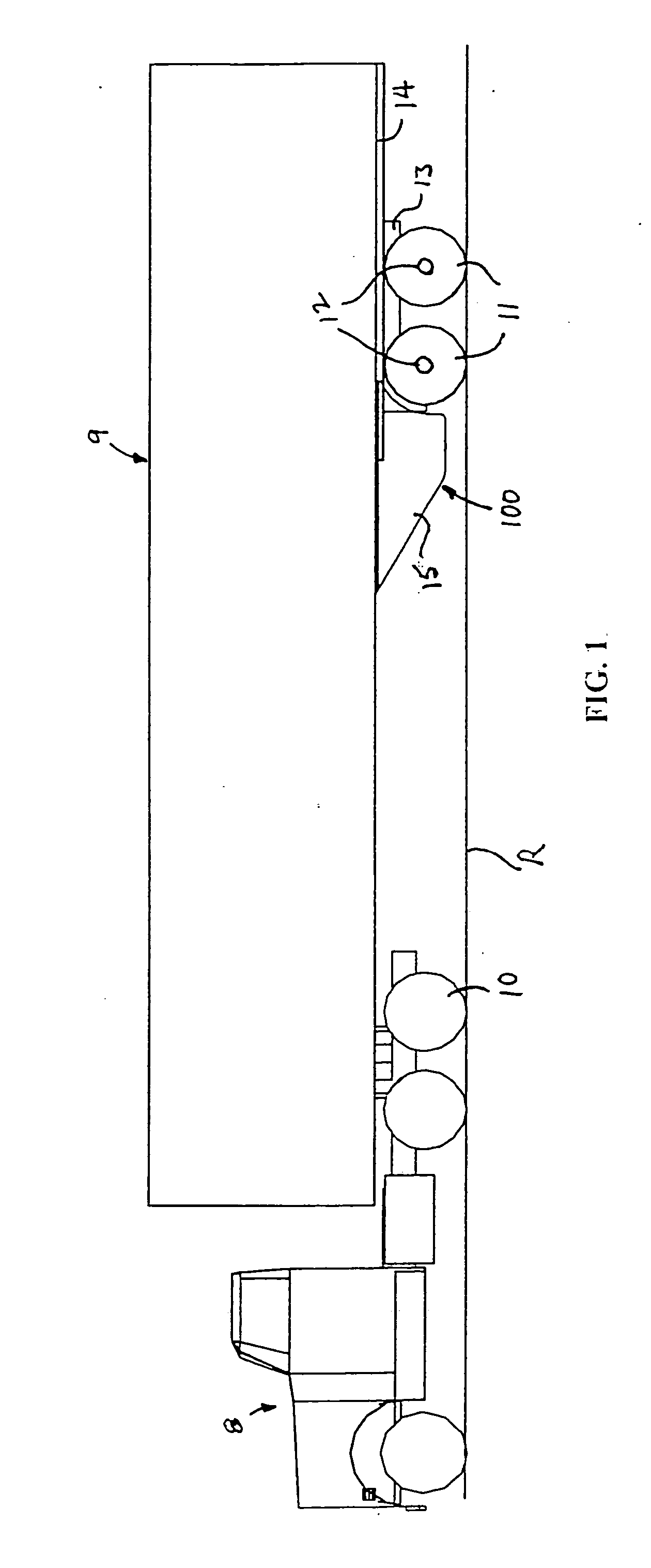
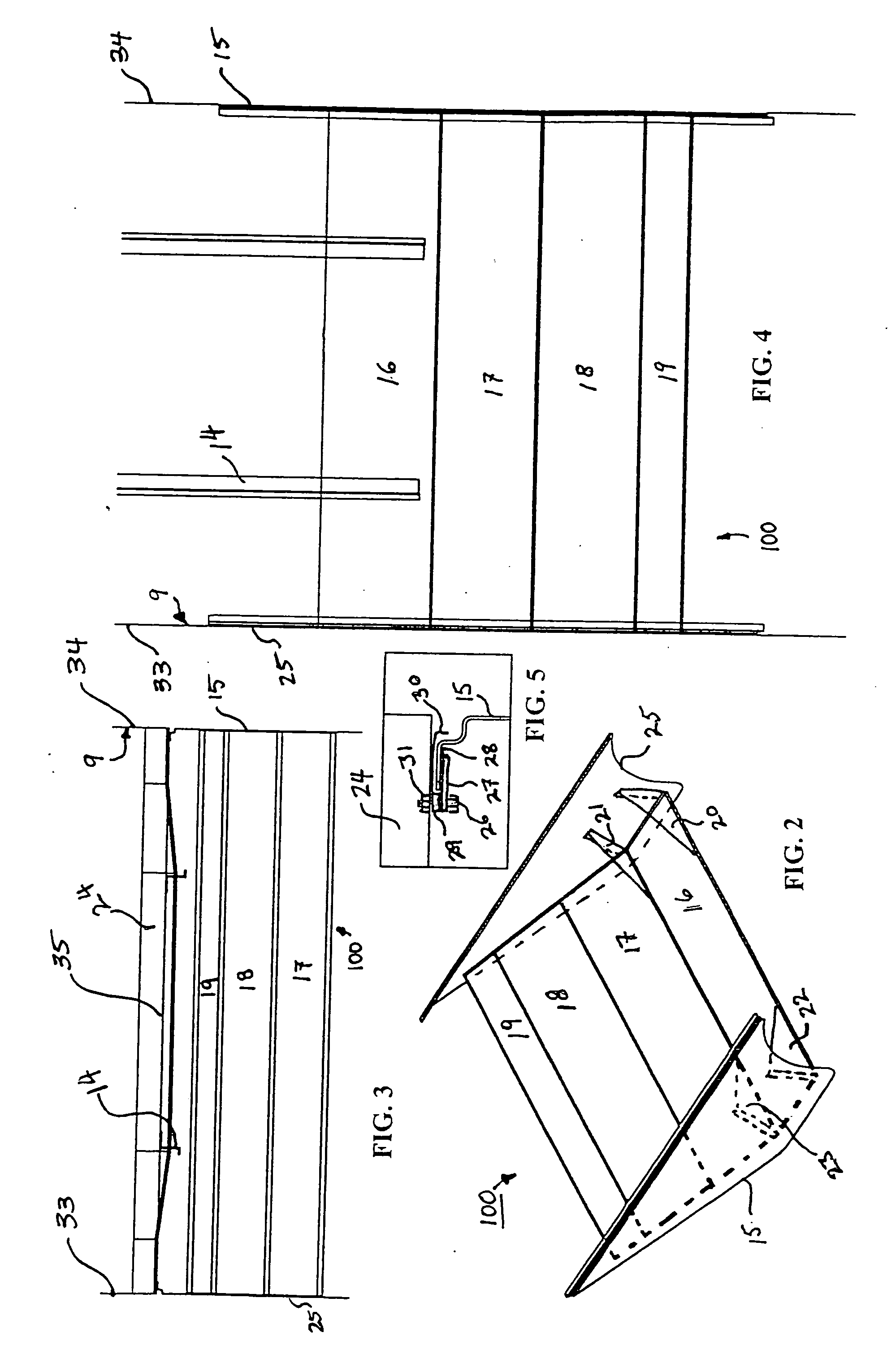
[0024]FIG. 1 is a somewhat schematic side elevation view showing a truck 8 and trailer 9 having an airflow control device I 00 constructed according to principles of the present invention. FIG. 2 is a somewhat schematic perspective view of the airflow control device 100 of FIG. 1, showing a preferred panel construction of the device 100. FIG. 3 is a somewhat schematic front elevation view of the airflow control device 100 of FIG. 1 arranged under the trailer 9, illustrating a relationship between the device 100 and an underside of the trailer 9.

[0025] Referring to FIG. 1, an airflow control device 100 preferably comprises an air deflec...


PUM


Abstract

An aerodynamic airflow control device is preferably mounted either in a rigid or slidable manner to an underside of a truck trailer just forward of the trailer tires and axles to better manage airflow around the trailer tire and axle assembly. In operation, the device preferably collects and routs impinging air to exit between the trailer tires and under the trailer axles to reduce road spray while keeping tires and brakes running cooler and while further decreasing parasitic drag of the truck and trailer unit as it moves along the highway.

Description

CROSS-REFERENCE TO RELATED APPLICATIONS [0001] This U.S. non-provisional patent application claims priority under 35 U.S.C. § 119 from U.S. Provisional Patent Application 60 / 678,810 filed May 9, 2005, the contents of which are hereby incorporated herein by reference in their entirety.BACKGROUND OF THE INVENTION [0002] This invention relates generally to heavy truck trailers, and more specifically to an airflow control device that provides spray and splash control of trailer tire assemblies. It is well known by highway travelers that truck and trailers kick up voluminous amounts of splash and spray whenever the highways are wet. Various solutions have been proposed as a way to control spray and splash from truck trailers. [0003] U.S. Pat. No. 4,262,953, issued Apr. 21, 1981 to McErlane (“McErlane”), shows undermounted air deflectors for truck trailers. These are airfoils or deflector panels mounted ahead of the rearmost set of wheels that direct the air down and around the deflector....

Claims


Application Information

Patent Timeline
Patent Type & Authority Applications(United States)
IPC IPC(8): B60H1/00
CPCB62D35/001
Inventor HENDERSON, ROBERT R. II
Owner AIRMAN
Learn More