
Fault-tolerant architecture for a distributed control system

a distributed control system and fault-tolerant technology, applied in the direction of braking systems, instruments, brake components, etc., can solve the problems of crash failures and omission failures, unique challenges related to system responsiveness, reliability and fault tolerance, and each node is considered to be fail-silent, so as to improve reliability and fault tolerance

Inactive Publication Date: 2006-11-09
GM GLOBAL TECH OPERATIONS LLC
View PDF41 Cites 45 Cited by
  • Summary
  • Abstract
  • Description
  • Claims
  • Application Information

AI Technical Summary

Benefits of technology

[0009] The present invention enhances reliability and fault-tolerance of a system comprising a distributed system architecture, such as a steer-by-wire system for a motor vehicle.
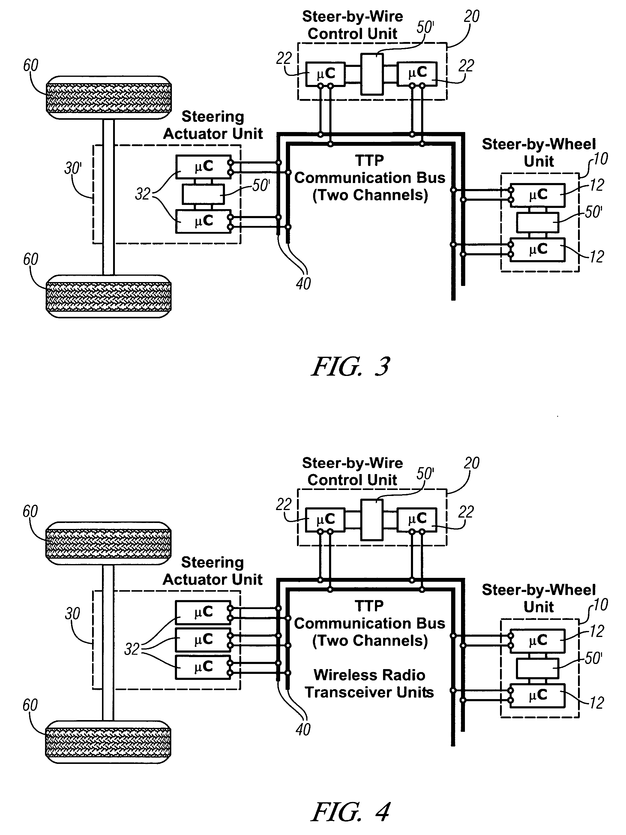
[0010] Providing a real-time fault-tolerant wireless networking architecture for the drive-by-wire functionality in automobiles improves system reliability. The wireless fault-tolerant architecture can provide backup capability, or complementary communications capability. This invention provides such a wireless architecture for next-generation vehicles. The novel drive-by-wire / wireless architecture uses multiple wireless sensors and short-range low-power radio transceivers associated with various micro-controllers in an electronic (i.e., drive-by-wire) vehicle. These sensors and radio transceivers allow the various micro-controllers to communicate critical vehicle control signals and drive commands, in the event of a physical breakdown of communications in the “wire” of the drive-by-wire system. This leads to improved levels of fault-tolerance to the drive-by-wire vehicle.

Problems solved by technology

However, applications, such as a drive-by-wire system utilizing a distributed control system architecture, pose unique challenges related to system responsiveness, reliability and fault tolerance.
Each node is considered to be fail-silent, i.e., only crash failures and omission failures can occur.
However, in the event that both communication buses fail at a point, the three FTUs of the steer-by-wire subsystem fail to communicate with each other, and consequently cease to function as intended.
In some cases, this may lead to compromised vehicle steering capability.

Method used


Image

  • Fault-tolerant architecture for a distributed control system
  • Fault-tolerant architecture for a distributed control system
  • Fault-tolerant architecture for a distributed control system

Examples


Embodiment Construction

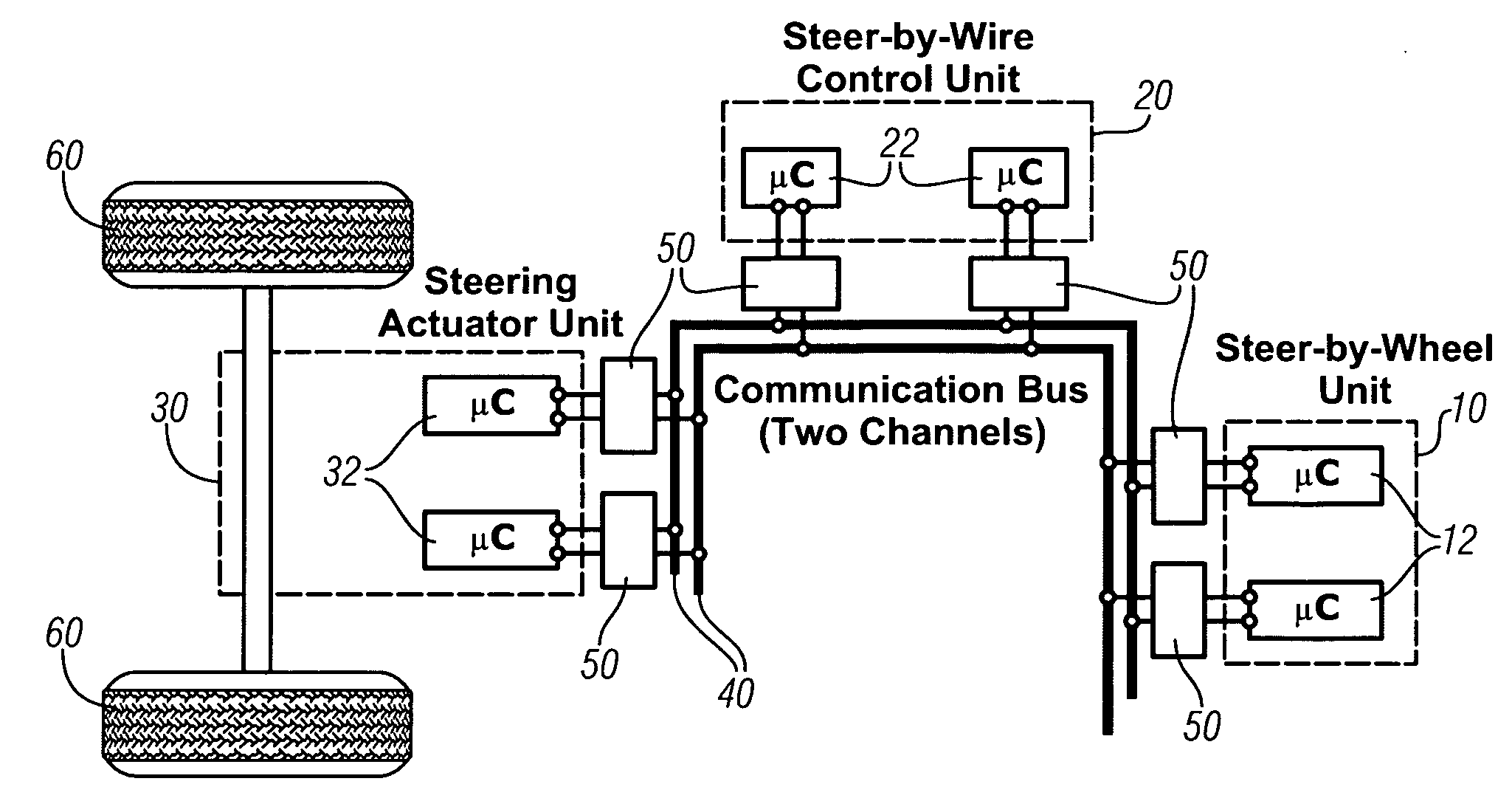
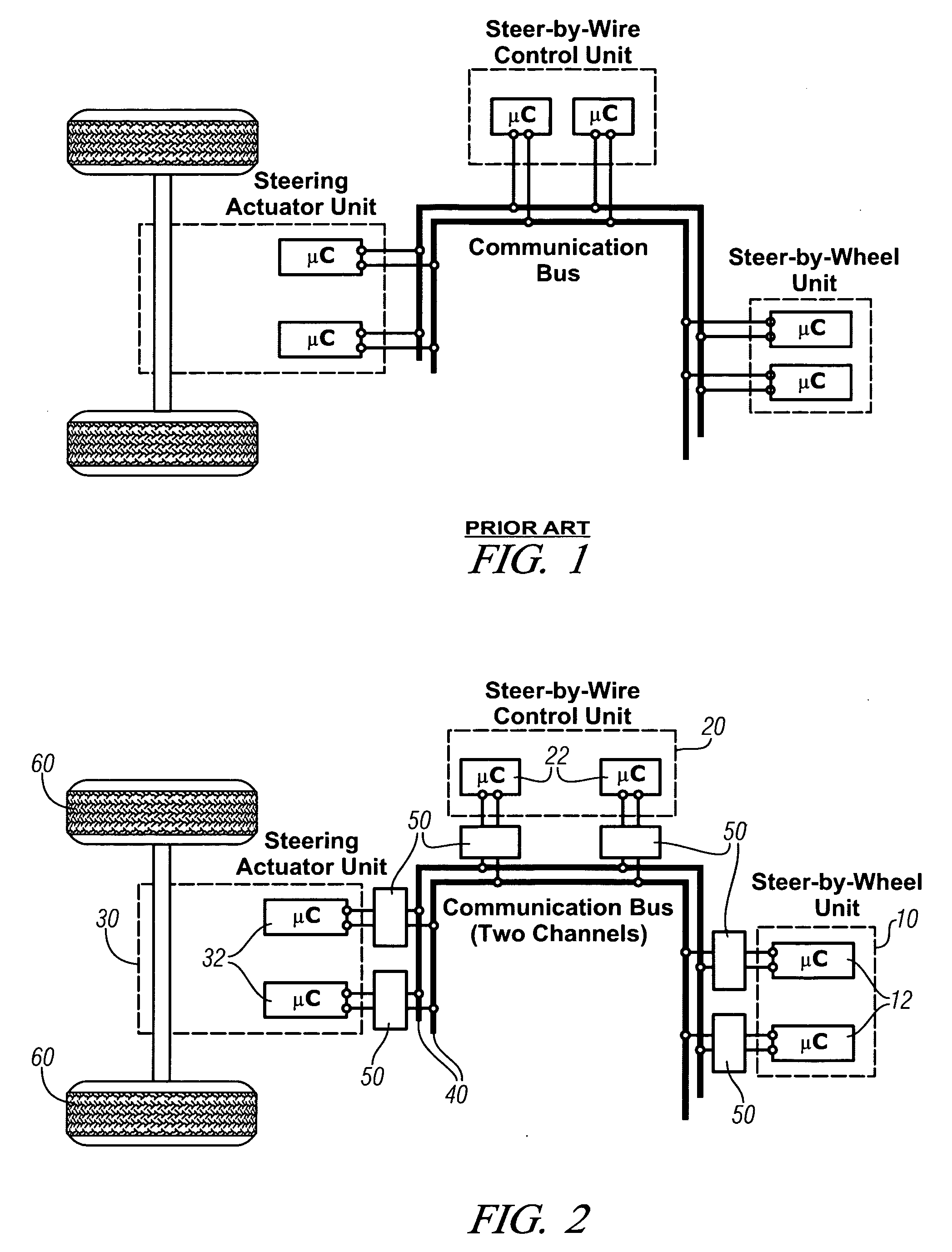
[0028] Referring now to the drawings, wherein the showings are for the purpose of illustrating the invention only and not for the purpose of limiting the same, FIGS. 2-6 shows exemplary embodiments of a fault-tolerant distributed control architecture in accordance with the invention described herein. The exemplary system comprises a control system for a steer-by-wire control system executed for use on a motor vehicle.

[0029] Referring now to FIG. 2, a schematic system of a fault-tolerant distributed system architecture for a steer-by-wire control system which has been constructed in accordance with a first embodiment of the present invention is shown. The FTUs of the exemplary system comprise a steer-by-wire or steering wheel unit 10, a steer-by-wire control unit 20, and a steering actuator unit 30. The steering wheel FTU 10 is operable to determine operator input regarding vehicle direction, and preferably includes fail-silent nodes comprising dual redundant sensors and microcontro...


PUM


Abstract

A fault-tolerant architecture, comprising fault tolerant units, a wire-based communication bus, and respective radio transceivers is offered. The fault-tolerant units communicate using the radio transceivers when communication via the wire-based communication bus is compromised by a fault. The intent is to enhance reliability and fault-tolerance of a distributed system architecture, such as a steer-by-wire system for a vehicle. The novel drive-by-wire / wireless architecture uses multiple wireless sensors and short-range low power radio transceivers associated with various micro-controllers. These sensors and radio transceivers allow the micro-controllers to communicate critical control signals and drive commands in the event of a communications fault, e.g. in a vehicle drive-by-wire system.

Description

CROSS-REFERENCE TO RELATED APPLICATIONS [0001] This application claims priority from U.S. Provisional Application No. 60 / 678,424, filed May 6, 2005, entitled WIRELESS ARCHITECTURE FOR DRIVE-BY-WIRE SYSTEMS.TECHNICAL FIELD [0002] This invention pertains generally to a distributed control system, and more specifically to a fault-tolerant control system useable in drive-by-wire systems for vehicles. BACKGROUND OF THE INVENTION [0003] Engineers are developing control systems for next-generation vehicles which employ electronic modules and electromechanical devices which replace mechanical systems, to reduce vehicle mass and improve responsiveness and controllability. Such electronic modules and electromechanical devices are typically executed in distributed system architectures. By way of example, a steer-by-wire system employs electric steering motors which are able to replace mechanical steering components including power steering pumps, hoses, hydraulic fluids, drive belts, and brake...

Claims


Application Information

Patent Timeline
IPC IPC(8): G06F11/00
CPCB60T2270/404G06F11/2005G06F11/202G06F11/2012G06F11/2007B62D5/001
Inventor KUKSHYA, VIKASHSU, HUI-PINTALTY, TIMOTHY J.
Owner GM GLOBAL TECH OPERATIONS LLC
Learn More