
Bonding Method of Ceramic Honeycomb Structure

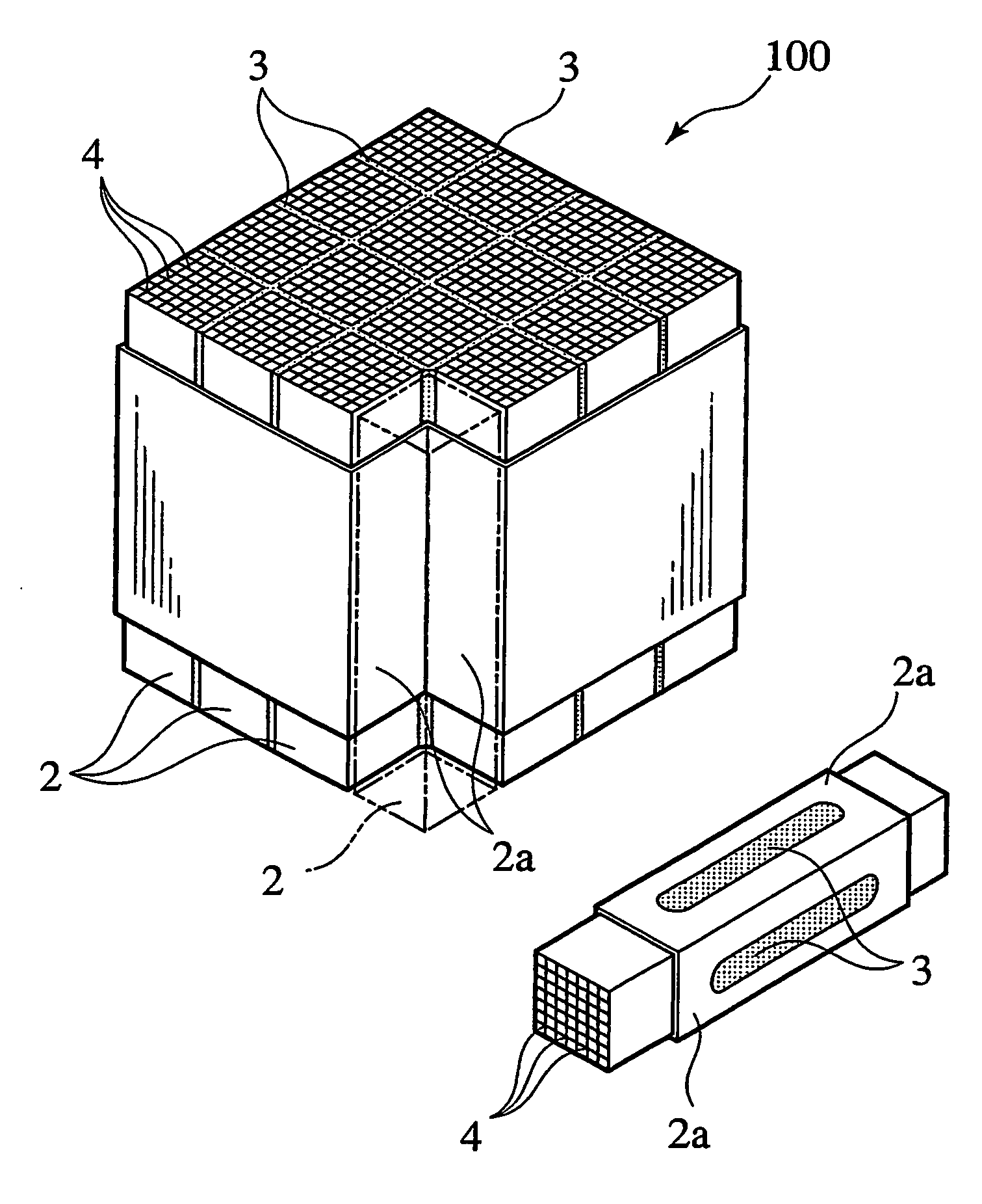
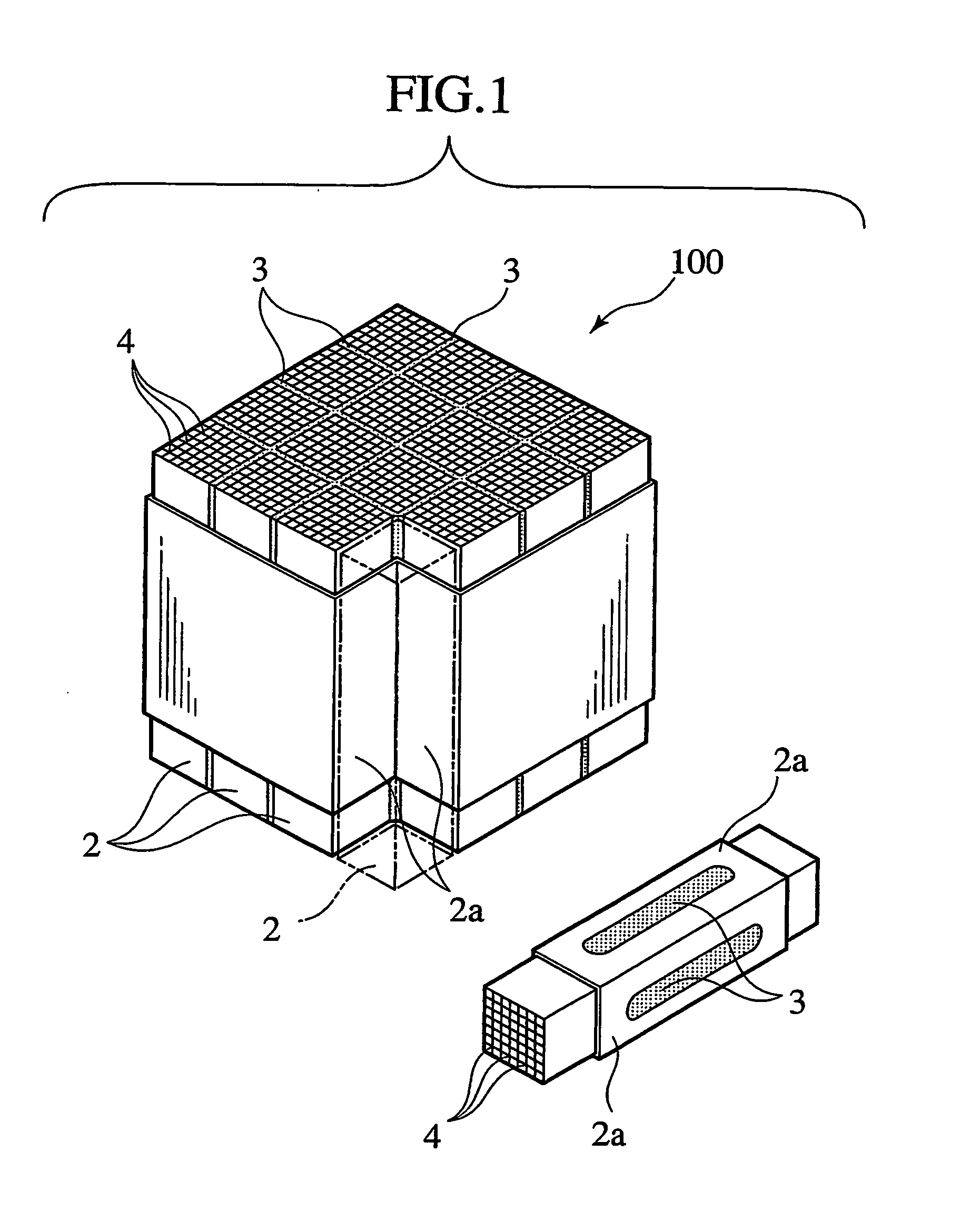
Active Publication Date: 2006-11-16
NGK INSULATORS LTD
View PDF2 Cites 17 Cited by
  • Summary
  • Abstract
  • Description
  • Claims
  • Application Information

AI Technical Summary

Benefits of technology

[0016] According to the second characteristic of the present invention, it is possible to allow bubbles trapped during the stacking to escape at the time of preliminary pressurization without causing movement of other bonded honeycomb segments.
[0018] For this reason, according to the third characteristic of the present invention, it is possible to prevent the honeycomb segments from being separated at the time of preliminary pressurization and to exert a bubble eliminating action as well.

Problems solved by technology

Accordingly, the method has a problem that the adhesive layers 3 for bonding the lower honeycomb segments are separated, thereby causing partial deterioration of adhesive strength.

Method used


Image

  • Bonding Method of Ceramic Honeycomb Structure
  • Bonding Method of Ceramic Honeycomb Structure
  • Bonding Method of Ceramic Honeycomb Structure

Examples


example 1

[0044]FIGS. 6A and 6B show a specimen honeycomb segment 2 (FIG. 6A), and a ceramic honeycomb structure 1 (FIG. 6B) which is formed by bonding 16 pieces of the specimen honeycomb segments 2 together while interposing the adhesive layers 3.

[0045] The specimen honeycomb segment 2 is formed into a quadratic prism having dimensions of a=35 mm, b=35 mm, and c=152 mm.

[0046] The adhesive constituting the adhesive layers 3 applied a composition of 39% by mass of SiC, 30% by mass of aluminosilicate, 20% by mass of colloidal silica, 1% by mass of an inorganic plasticizer, and 10% by mass of water, which had viscosity of 350 p.

[0047] As for the bonding method, the one applying the bonding method shown in FIGS. 3A and 3B was defined as Example 1, and one applying a bonding method configured to stack the honeycomb segments 2 one-by-one and to give pressure and vibration at the time of stacking was defined as Comparative Example 1.

[0048] Bonding Conditions:

[0049] In Example 1, the main pressu...

examples 1 , 2

EXAMPLES 1, 2, and 3

[0054] Example 1 applies the bonding method shown in FIGS. 3A and 3B. Example 2 applies the bonding method shown in FIGS. 5A and 5B in which the preliminary pressurization force was set to 0.25 kgf / cm2. Example 3 applies the bonding method shown in FIGS. 5A and 5B in which the preliminary pressurization force 2 was set to 0.5 kgf / cm . Comparative Example 2 applies the bonding method shown in FIGS. 5A and 5B in which the preliminary pressurization force was set to 1 kgf / cm2. Comparative Example 3 applies the bonding method shown in FIGS. 5A and 5B in which the preliminary pressurization force was set to 1.5 kgf / cm2. Comparative Example 4 applies the bonding method shown in FIGS. 5A and 5B in which the preliminary pressurization force was set to 2 kgf / cm2. Comparative Example 5 applies the bonding method shown in FIGS. 5A and 5B in which the preliminary pressurization force was set to 2.5 kgf / cm2.

[0055] At this time, the main pressurization in Examples 1, 2, and 3...


PUM

PropertyMeasurementUnit
Pressureaaaaaaaaaa
Forceaaaaaaaaaa
Pressureaaaaaaaaaa

Abstract

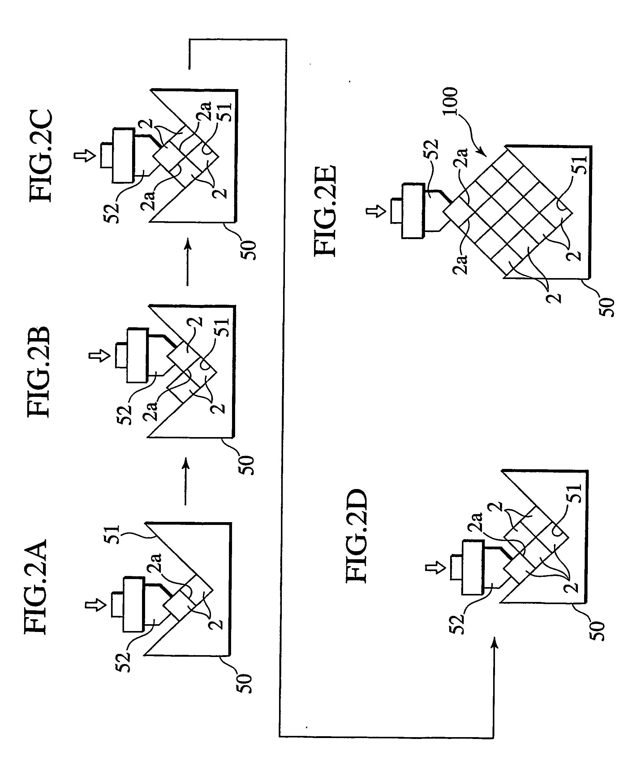
Respective pieces of the porous honeycomb segments (2) are stacked while interposing the adhesive layers between respective adhered surfaces (2a), and are bonded together by performing main pressurization (F1, F2) on the whole through the porous honeycomb segments (2) located on an outermost layer after stacking a predetermined number of pieces. Main pressurization force at this time is simultaneously applied to all the honeycomb segments (2) and does not act as a separating force against any of the honeycomb segments (2).

Description

TECHNICAL FIELD [0001] The present invention relates to a bonding method of a ceramic honeycomb structure, which is used for filters for collecting particles in exhaust gases from inner combustion engines and boilers as well as catalyst bearers utilizing a catalyst to be used for chemical reactors, fuel cell reformers and the like. BACKGROUND ART [0002] As shown in FIG. 1, a ceramic honeycomb structure 100 of this type is formed by bundling a plurality of porous honeycomb segments 2 through adhesive layers 3, where the porous honeycomb segments 2 are provided with numerous circulation holes 4 partitioned by partition walls and penetrated in an axial direction. [0003] Document 1: Japanese Unexamined Patent Publication No. 2000-7455 [0004] Specifically, the ceramic honeycomb structure 100 is formed by mutually bonding sixteen pieces of the porous honeycomb segments 2 each in a quadratic prism shape into a four-by-four matrix through the adhesive layers 3. [0005] Bonding at this time i...

Claims


Application Information

Patent Timeline
IPC IPC(8): B32B37/12C09J5/00B01D39/20B01D46/00B01D46/24C04B35/80C04B37/00C04B38/00
CPCB01D46/0001Y10T428/24149B01D46/2459C04B35/565C04B35/62625C04B35/6263C04B35/632C04B35/806C04B37/005C04B38/008C04B2111/00793C04B2111/0081C04B2235/3418C04B2235/3826C04B2235/5228C04B2235/668C04B2235/80C04B2235/96C04B2237/083B01D46/2418C04B38/0006C04B35/80B01D46/2478C04B37/003B01D39/2068B01D46/2466B01D46/249
Inventor FUJITAKANEKO, TAKAHISAWADA, YUKIHISA
Owner NGK INSULATORS LTD
Learn More