Spectrometer chip assembly

a spectrometer and chip technology, applied in the field of spectrometry, can solve the problems of complex systems, high cost of mass spectrometers, and difficult field deployment of mass spectrometers

Inactive Publication Date: 2006-11-16
CHARLES STARK DRAPER LABORATORY
View PDF2 Cites 33 Cited by
  • Summary
  • Abstract
  • Description
  • Claims
  • Application Information

AI Technical Summary

Benefits of technology

[0052] Preferably, an ion mobility filter system defines a spectrometer chip with a pair of electrode-carrying surfaces facing each other across a gap, the gap influenced by a spacer part, the substrate surfaces and the spacer part cooperating to form a flow channel, including at least a pair of filter electrodes facing each other across the gap, an ion supply region, ions from the region flowing in the flow channel and having a flow path passing between the filter electrodes, the filter electrodes applying compensated asymmetric mobility-controlling fields across the gap, the filter filtering the ions according to their mobility in the fields, with selected ions with selected mobility passing though the filter, and electrical contacts through which an asymmetric periodic voltage is applied to the ion filter electrodes for generating the fields and controlling the filtering. Preferably the flow channel is hermetically sealed (except, of course, at the inlet and outlet), so as to minimize sample loss.
[0091] Application of embodiments of the invention enable robust, compact, reduced cost, high performance, chemical detection and analysis systems. These are operable in laboratory and factory locations, as well as on-board in mobile equipment and mobile installations. Portable equipment in practice of the invention includes chemical detectors and explosives sensors, and the like. It will be appreciated that the term flow channel refers to a physical structure such as a channel defined in cooperation with substrates to form a flow channel. The flow path is the path that the sample travels from inlet to outlet, which includes travel in the flow channel. The terms flow path and flow channel may be used interchangeably in the following description and still remain in the scope of the invention.

Problems solved by technology

Mass spectrometers are expensive, easily exceeding $100K, and are difficult to deploy in the field.
Mass spectrometers also suffer from the need to operate at low pressures resulting in complex systems, and their spectra can be difficult to interpret often requiring a highly trained operator.
As well, the GC-MS is not well suited for small, low cost, fieldable instruments.
Widespread use still remains a problem for TOF-IMS.
Despite advances over the past decade, TOF-IMS flow channels (also referred to as drift tubes) are still comparatively large and expensive and suffer from losses in detection limits when made small.
The device has been found to be complex, with many parts, and somewhat limited in utility.
This can be a serious problem when coupling to a prefilter or separator, such as a GC.
A GC operates so rapidly that known FAIMS devices cannot generate a complete spectra of the ions present under each GC peak.
Therefore these prior art FAIMS devices would have to be limited to a single compound detection mode if coupled to a GC, with a response time of about 10 seconds.

Method used


Image

  • Spectrometer chip assembly
  • Spectrometer chip assembly
  • Spectrometer chip assembly

Examples


Embodiment Construction

[0136] A description of preferred embodiments of the invention follows.

[0137] The present invention provides apparatus for the analysis of compounds using principals of high field asymmetric waveform ion mobility spectrometry (FAIMS). Preferably, the apparatus is a spectrometer chip or spectrometer engine that performs the FAIMS function and provides a useful output representative of filtered ions.

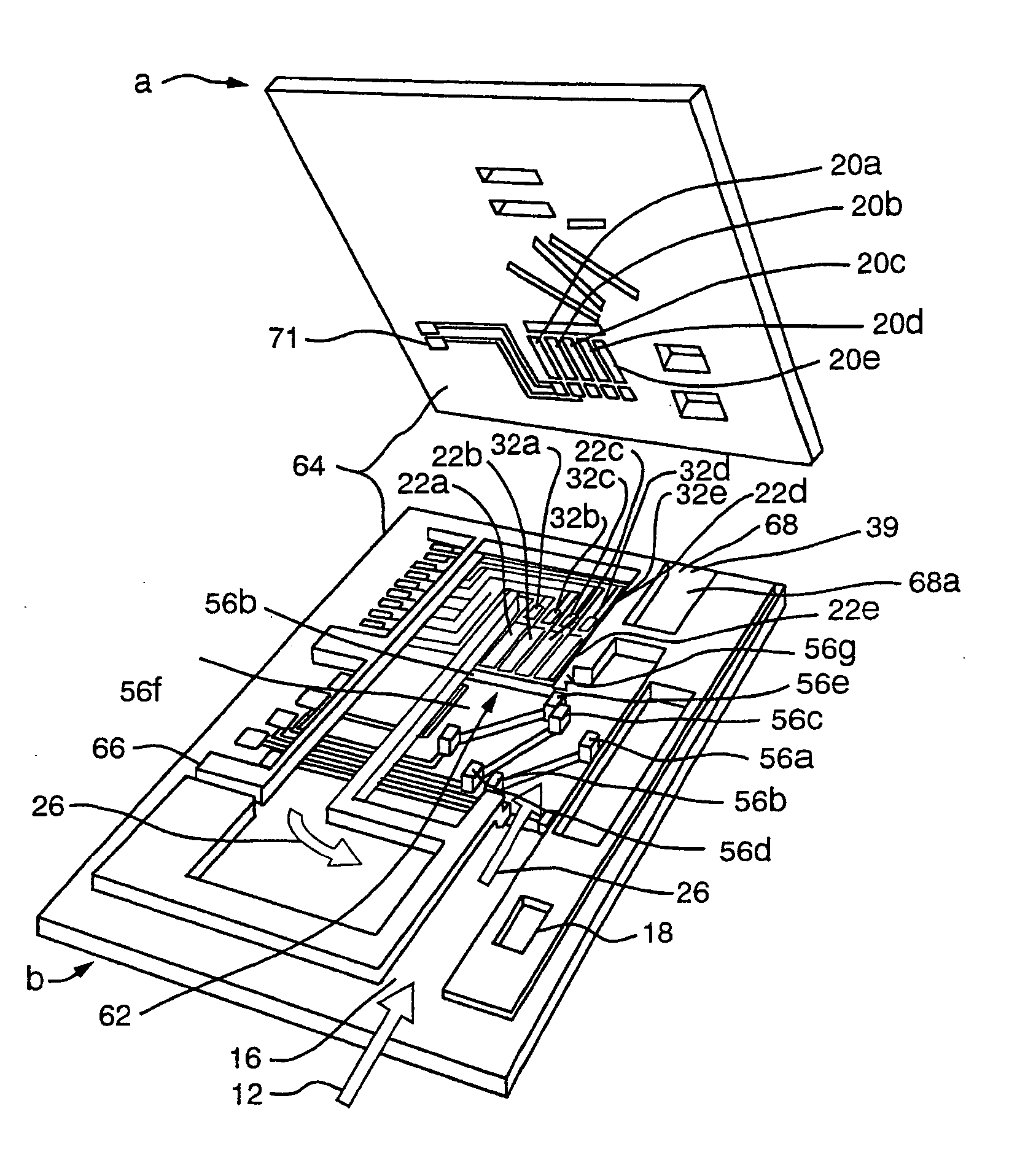
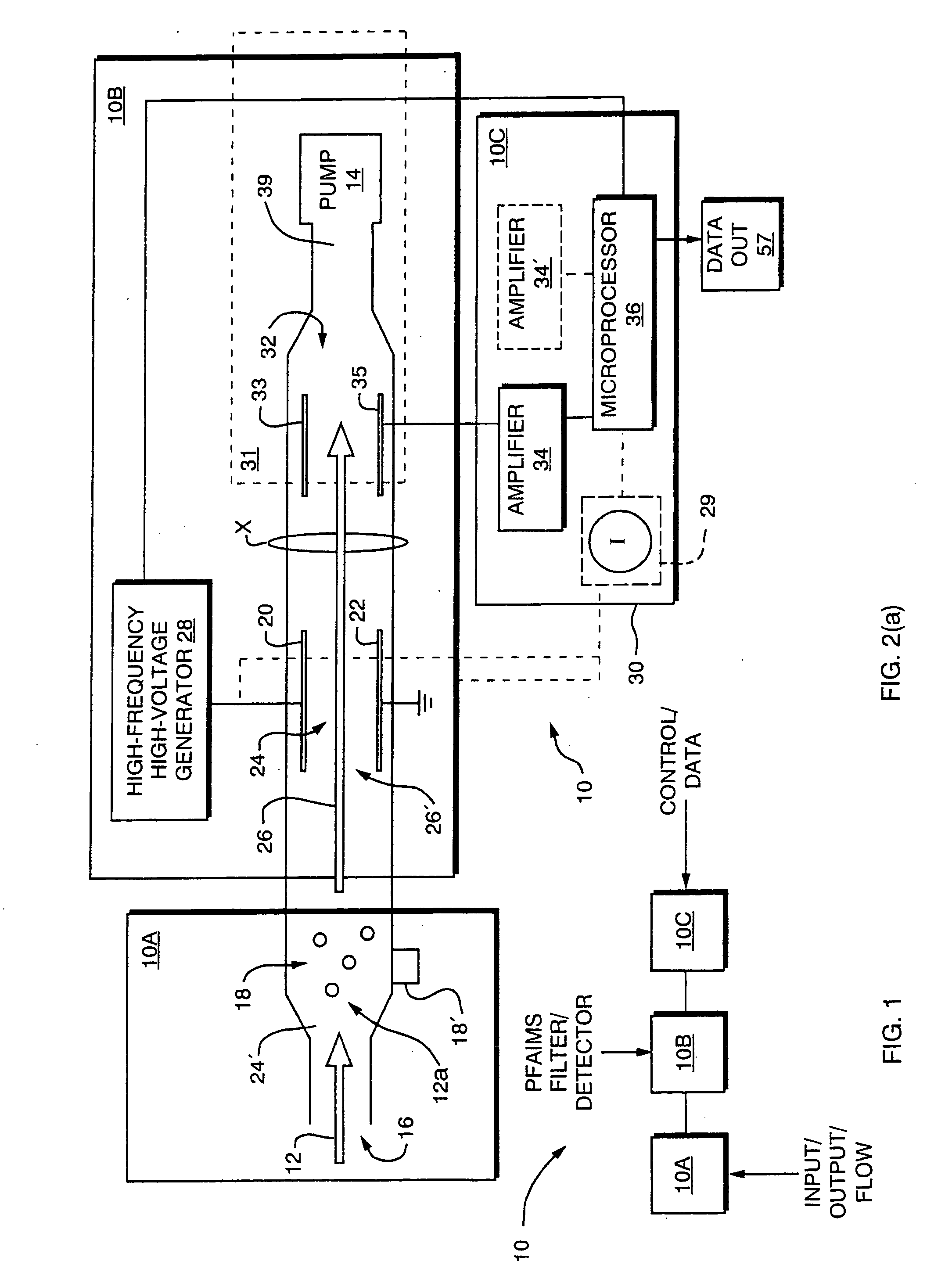
[0138] As shown in FIG. 1, a Planar FAIMS (PFAIMS) chemical sensor system 10 according to the invention includes front end section 10A, electrode section 10B, and control section 10C. Front end section 10A may open directly to the environment for receipt of samples or may receive conditioned samples, such as those eluting from a liquid or gas chromatograph or the like, and then provides ionized samples to filter / detector section 10B for filtering and detection of ions, all under control of control section 10C.

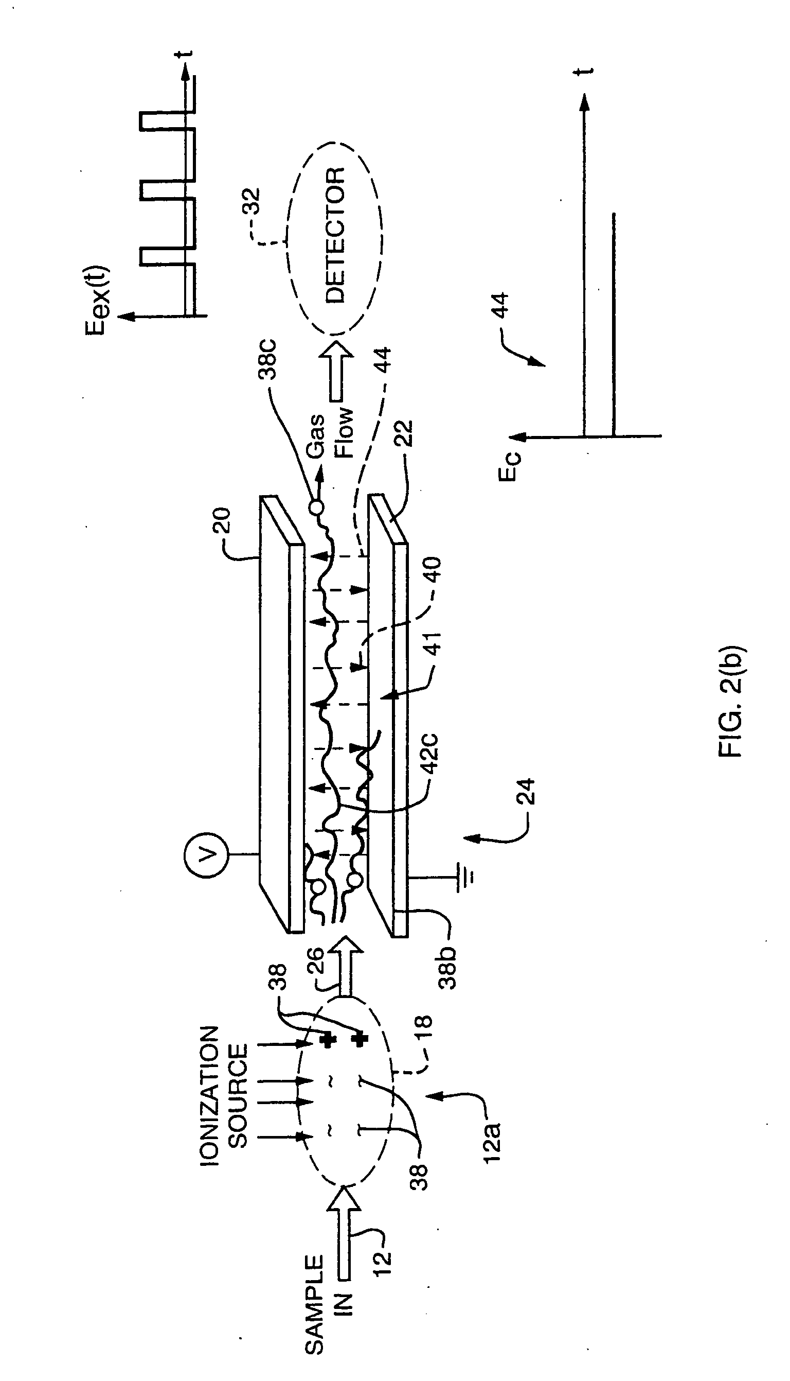
[0139] In one embodiment, shown in the schematic of FIG. 2(a), front end secti...


PUM


Abstract

Method and apparatus for high field asymmetric waveform ion mobility spectrometry in an electronic chip assembly, including an input section, an ion filter and detection section and a control section, in which ion filtering proceeds in a planar chamber under influence of high field asymmetric periodic signals, with detection integrated into the flow path, for producing accurate, real-time, data for identification of a broad range of chemical compounds.

Description

REFERENCE TO RELATED APPLICATIONS [0001] This application is a Continuation Application of U.S. application Ser. No. 10 / 836,432, filed Apr. 30, 2004, which is a Continuation-in-Part of U.S. application Ser. No. 10 / 205,667, filed Jul. 25, 2002, which is a continuation of U.S. application Ser. No. 09 / 882,883, filed Jun. 15, 2001. The U.S. application Ser. No. 10 / 836,432 is also a continuation-in-part of U.S. application Ser. No. 10 / 321,822, filed Dec. 16, 2002, which is a continuation-in-part of U.S. application Ser. No. 09 / 358,312, filed Jul. 21, 1999, the latter now issued as U.S. Pat. No. 6,495,823. The U.S. application Ser. No. 10 / 836,432 is also a continuation-in-part of U.S. application Ser. No. 10 / 082,803, filed Feb. 21, 2002, which is a continuation-in-part of U.S. application Ser. No. 09 / 358,312, filed Jul. 21, 1999 and a continuation-in-part of U.S. application Ser. No. 09 / 439,543, filed Nov. 12, 1999, the latter now issued as U.S. Pat. No. 6,512,224. The contents of all of ...

Claims


Application Information

Patent Timeline
Patent Type & Authority Applications(United States)
IPC IPC(8): H01J49/00
CPCH01J49/0018G01N27/624
Inventor MILLER, RAANAN A.ROBBINS, WILLIAM L.
Owner CHARLES STARK DRAPER LABORATORY
Why Eureka
Try Eureka