Shielded, asymmetric magnets for use in magnetic resonance imaging
a magnetic resonance imaging and shielding technology, applied in the field of shielded, asymmetric superconducting and non-superconducting magnets, can solve the problems of high cost, many people suffer from claustrophobia, and physicians cannot easily assist or personally monitor subjects during mri procedures, and achieves the effects of convenient use, reduced cost, and improved imaging performan
- Summary
- Abstract
- Description
- Claims
- Application Information
AI Technical Summary
Benefits of technology
Problems solved by technology
Method used
Image
Examples
example 1
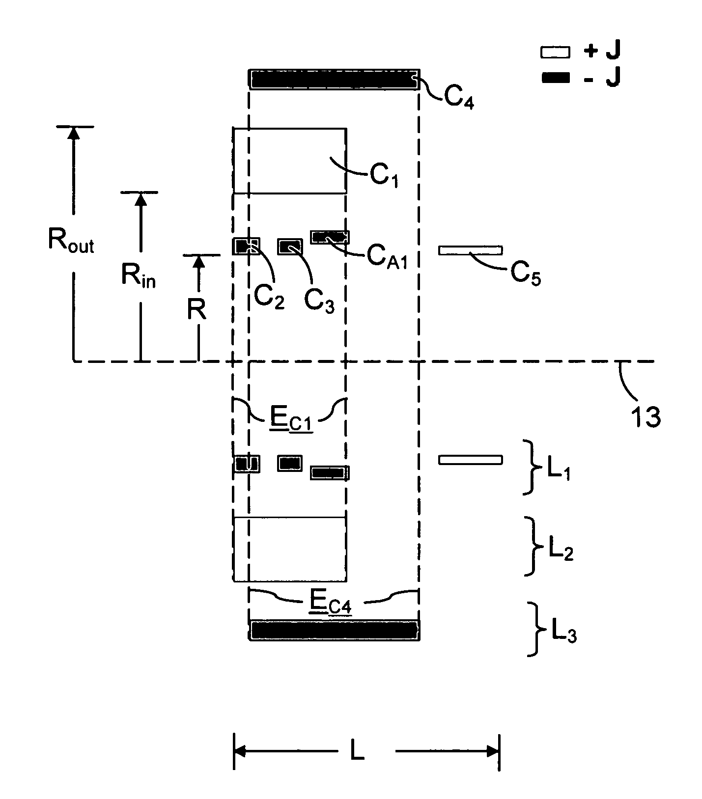
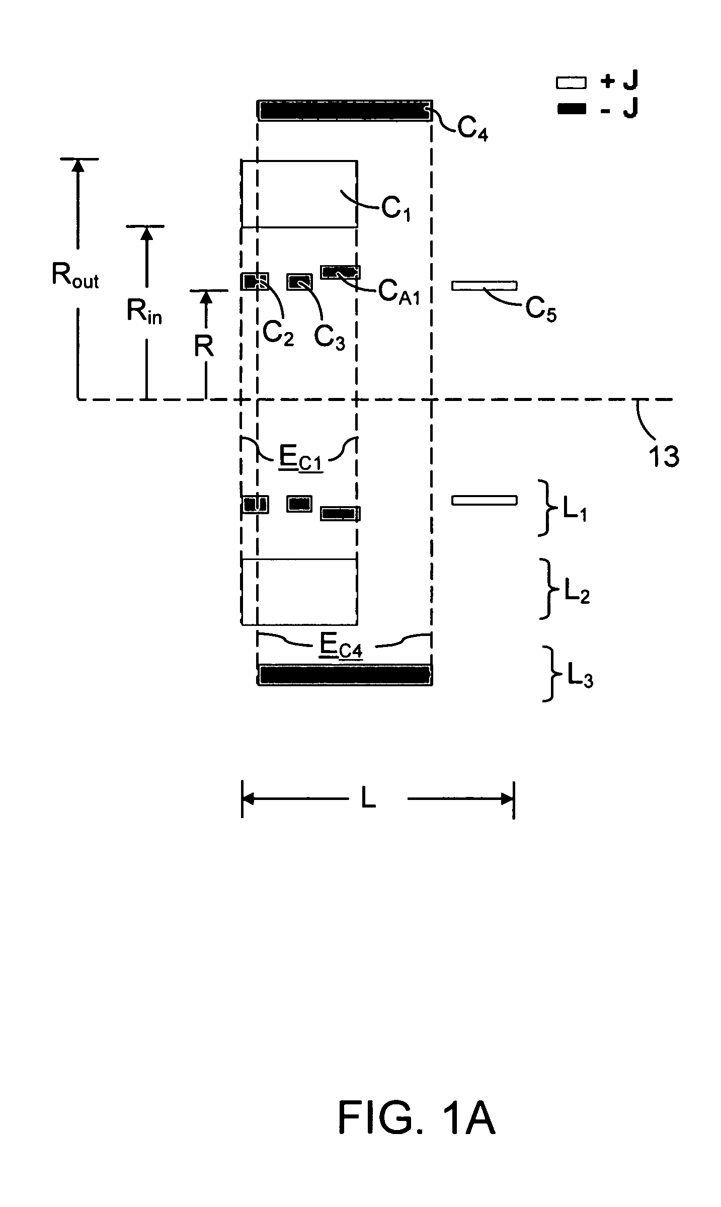
[0110] This example illustrates an asymmetric, superconducting magnet of the present invention. In broad overview, the magnet employs six coils and has a cold bore length (L) and a cold bore inner radius (R) of approximately 0.5 and 0.18 meters, respectively. The magnet employs a positive coil (C5) at the magnet's distal end, and three negative coils located near the magnet's proximal end, all of which are at least partially within the internal envelope (EC1) defined by the magnet's strongest coil (the C1 coil). The magnet employs active shielding provided by coil C4. Two of the magnet's coils (C1 and C4) have lower current densities than the remaining coils.
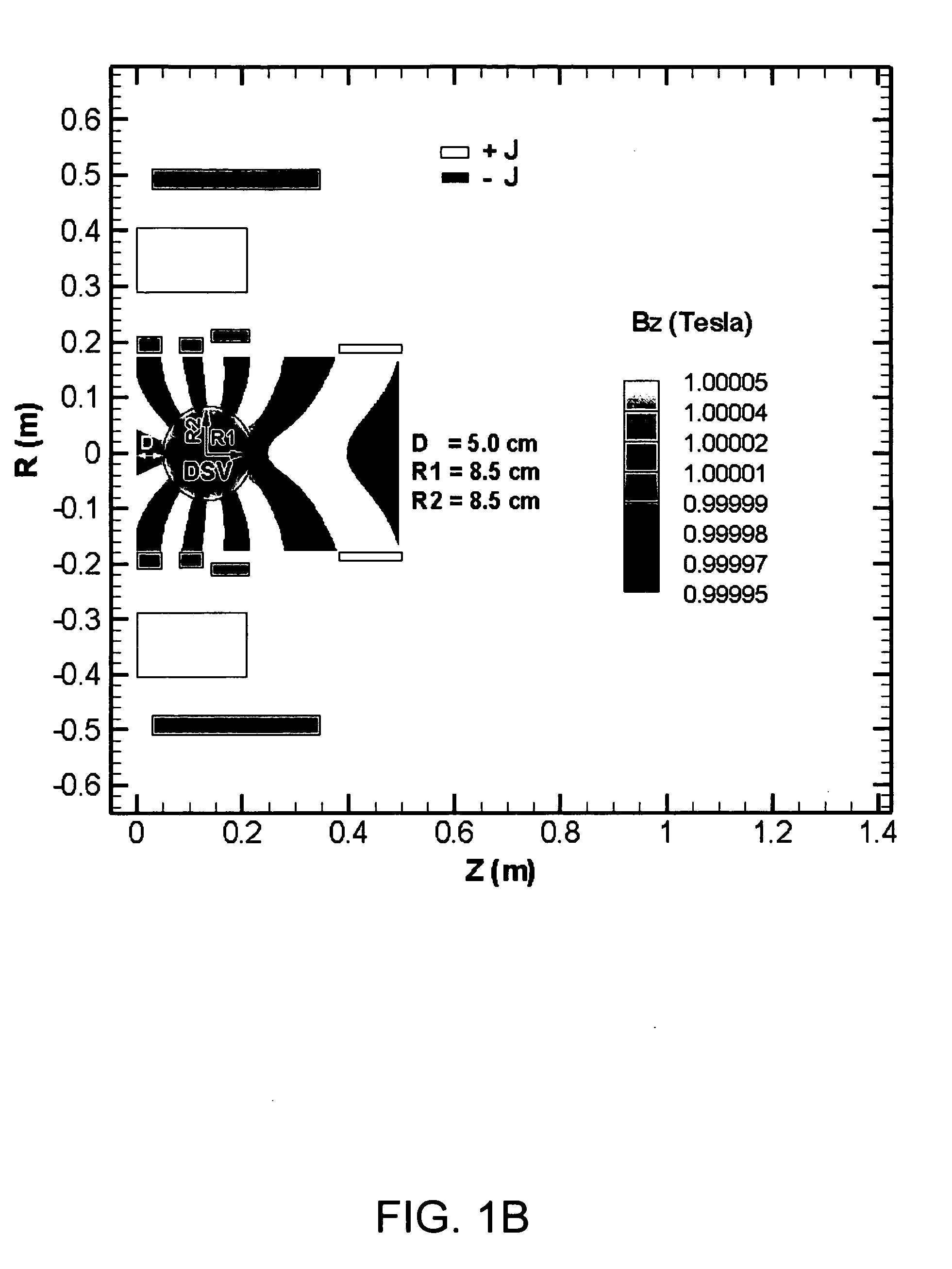
[0111]FIG. 1A shows the six coils used in the magnet, FIG. 1B shows the calculated axial magnetic field generated by the magnet, including the magnet's dsv, FIG. 1C shows the calculated magnitudes of the total magnetic field generated by the magnet within the magnet's various coils, FIG. 1D shows the calculated hoop stresses in...
example 2
[0117] This example illustrates a superconducting magnet in which the current density is increased compared to Example 1. Specifically, in Example 1, the current density was 80 amps / mm2 in some coils, while in this example, the current density is 120 amps / mm2 in all coils.
[0118] As shown in FIG. 2A, the strongest coil is now smaller than in Example 1, and instead of three negative coils located near the proximal end of the magnet, the magnet of this example only uses two such coils. However, the magnet now includes an additional positive coil (CA2) so that the total number of coils is again six.
[0119] As in Example 1, the magnet of this example has a cold bore length (L) and a cold bore inner radius (R) of approximately 0.5 and 0.18 meters, respectively. Again like Example 1, the magnet employs active shielding provided by coil C4.
[0120] As shown in FIGS. 2B-2E, the performance of the magnet is substantially the same as that of Example 1, except that the calculated hoop stresses ...
example 3
[0121] This example illustrates a magnet in which a combination of active and passive shielding is used. Specifically, this example uses an active shielding coil C4 in combination with a ferromagnetic structure FS to produce a low level of stray fields (see FIG. 3E).
[0122] As shown in FIG. 3A, the strongest coil (C1) is again smaller than that used in Example 1. As in Example 2, the magnet has two negative coils (C2 and C3) located near the proximal end of the magnet and an additional positive coil (CA2) which brings the total number of coils used in the magnet to six.
[0123] Table 2 shows the coil geometry and the magnitudes of the current densities in each coil for a constant transport current of 180 amperes. As shown in this table, the current density for each of the coils is 120 amps / mm2. Compared to Example 2, which also used a current density of 120 amps / mm2 for each of its coils, this example exhibits lower calculated hoop stresses because of the use of the ferromagnetic str...
PUM
 Abstract
Description
Claims
Application Information
 - R&D
- Intellectual Property
- Life Sciences
- Materials
- Tech Scout
- Unparalleled Data Quality
- Higher Quality Content
- 60% Fewer Hallucinations
Browse by: Latest US Patents, China's latest patents, Technical Efficacy Thesaurus, Application Domain, Technology Topic, Popular Technical Reports.
© 2025 PatSnap. All rights reserved.Legal|Privacy policy|Modern Slavery Act Transparency Statement|Sitemap|About US| Contact US: help@patsnap.com


