

Optical scanning method and system and method for correcting optical aberrations introduced into the system by a beam deflector
a beam deflector and optical scanning technology, applied in the field of optical scanning, can solve the problems of elliptical beam shape error, introduction of additional aberrations into the optical system, and inability to detect the shape of the elliptical beam, so as to achieve the effect of improving imaging
- Summary
- Abstract
- Description
- Claims
- Application Information
AI Technical Summary
Benefits of technology
Problems solved by technology
Method used
Image

Examples
Embodiment Construction
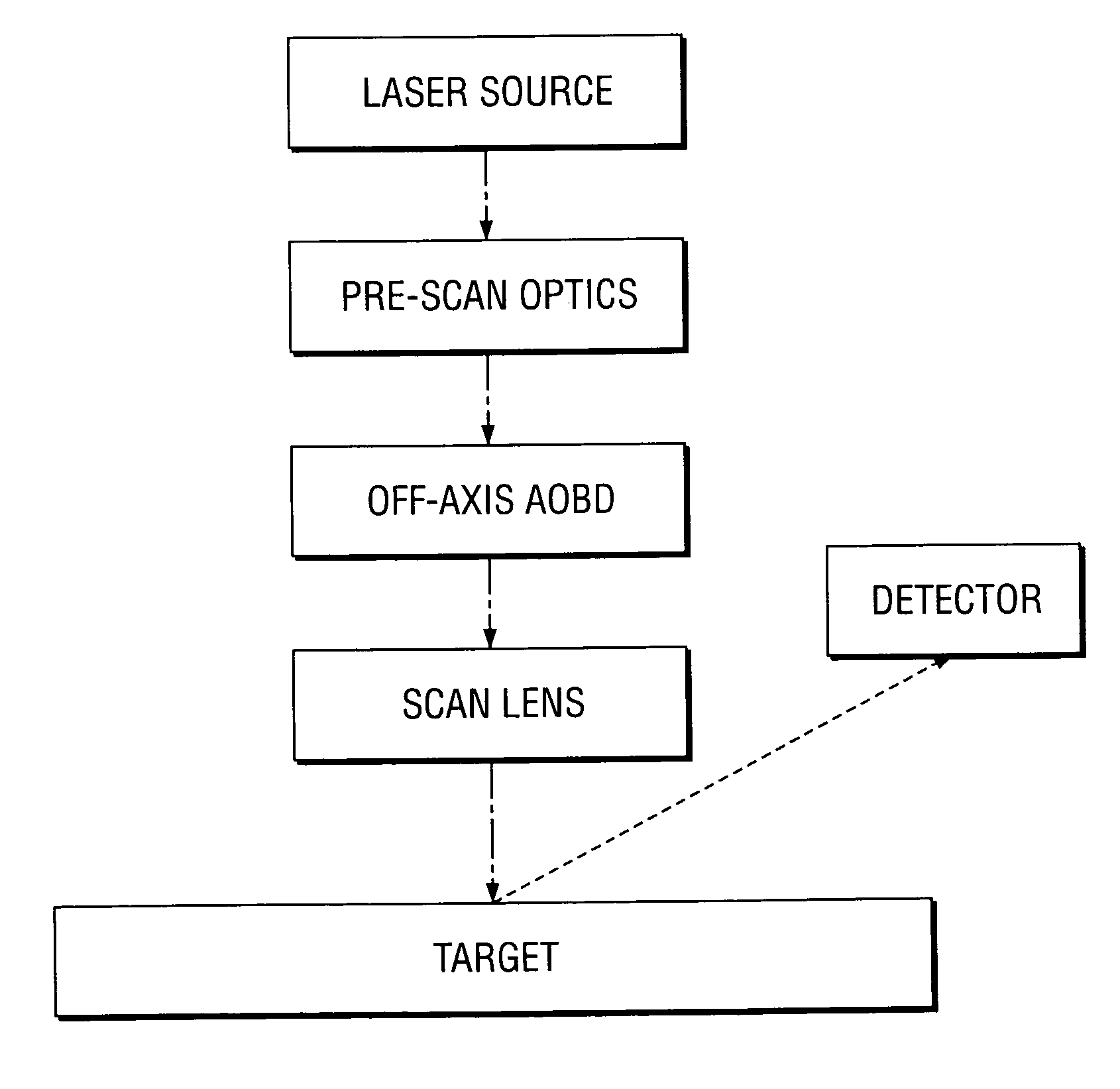
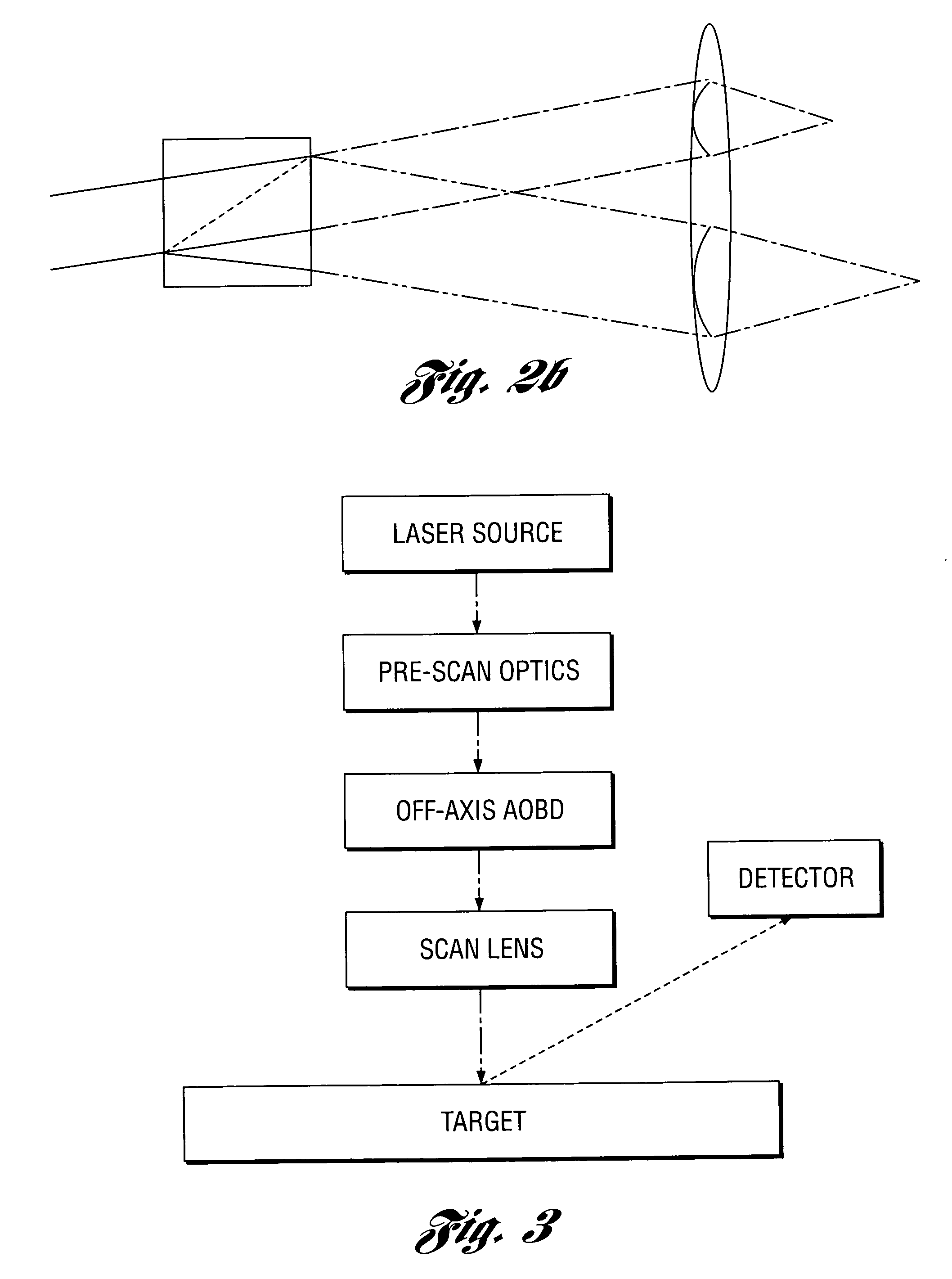
[0014] An aspect of the present invention provides an improved optical scanning method and system and method for correcting optical aberrations introduced into the system by a beam deflector such as an off-axis AOBD.
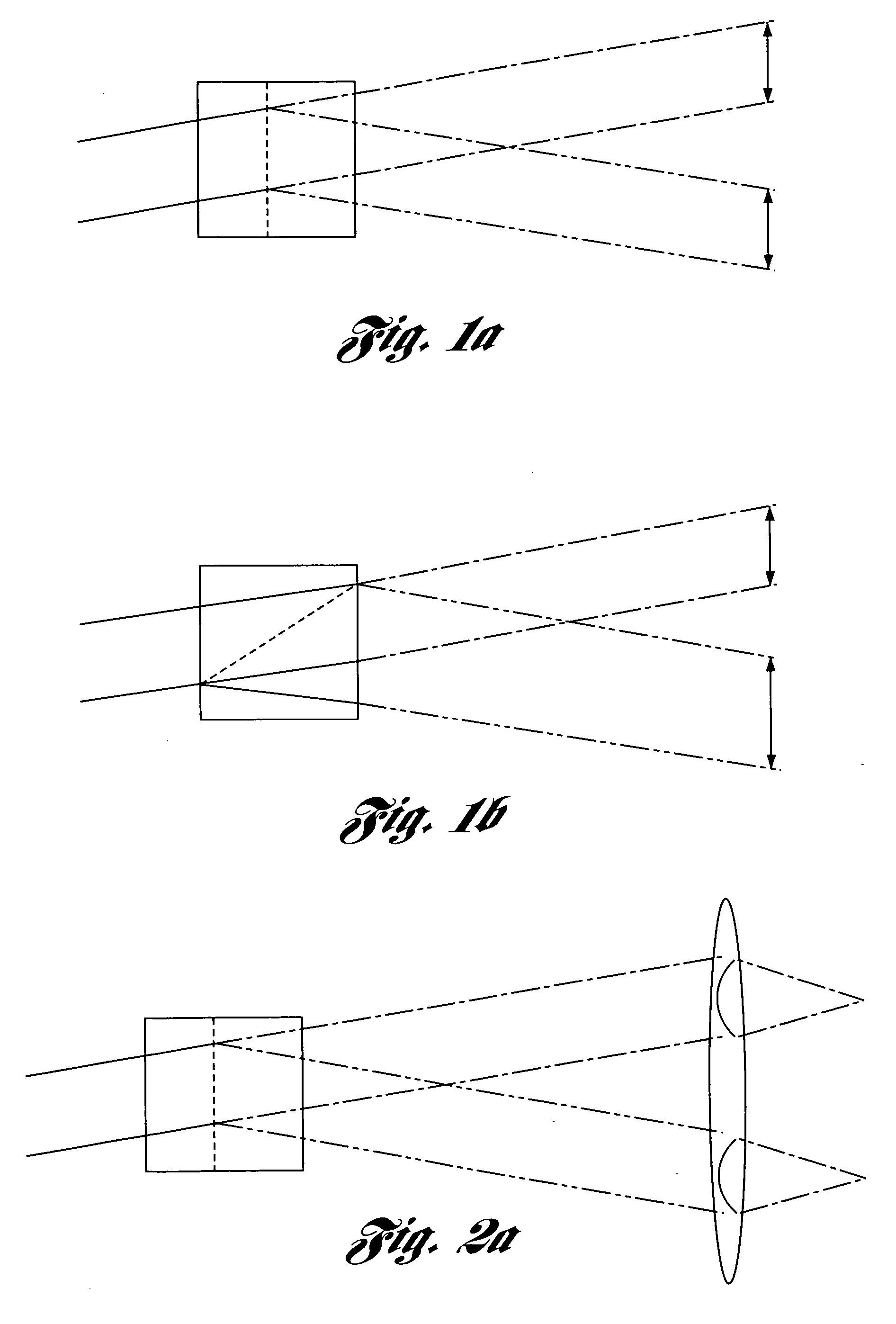
[0015] In carrying out the above aspect and other aspects of the present invention, a method for correcting optical aberrations introduced by a controllable beam deflector of an optical scanning system is provided. The system has an optical axis and a chirp dispersion rate. The method includes tilting at least one lens element disposed between the beam deflector and an image field of the system relative to the optical axis about a cross scan axis to introduce sufficient tilt to a scan focus to at least partially correct for focus tilt introduced by the beam deflector during scanning and thereby improve imaging.
[0016] The system may have approximately no residual focus tilt after the step of tilting.
[0017] The system may have residual focus tilt after the step of tilti...
PUM
 Abstract
Description
Claims
Application Information