Optical collimator

a collimator and optical technology, applied in the field of optical collimators, can solve the problems of inability to obtain stable optical performance, inability to manufacture, and inability to meet the requirements of optical communication devices using single-mode optical fibers or the like, and achieve the production of compact and high-precision metal eccentric sleeves for optical communication devices

Inactive Publication Date: 2006-11-16
NIPPON ELECTRIC GLASS CO LTD
View PDF2 Cites 8 Cited by
  • Summary
  • Abstract
  • Description
  • Claims
  • Application Information

AI Technical Summary

Benefits of technology

[0049] When the maximum diameter of the optical collimator 21 according to the present invention, such as the outer diameter of the eccentric sleeve 22, is less than 2 mm, miniaturization of an optical device using the optical collimator 21 and high-density arrangement of the optical collimators 21 become possible.

Problems solved by technology

When an eccentric sleeve used for an optical collimator is made of a metal, significant expansion / shrinkage occurs with respect to changing of an ambient temperature and an optical path length changes accordingly, so it becomes impossible to obtain stable optical performance.
Also, in order to produce a high-precision metal-made eccentric sleeve, it is required to conduct grinding work with accuracy of the order of micrometers on each sleeve using a precision cylindrical grinding machine or the like, which is problematic in terms of supply capacity and manufacturing cost.
In reality, however, production itself of compact and high-precision metal-made eccentric sleeves used for optical communications devices using single-mode optical fibers or the like is almost impossible.

Method used


Image

  • Optical collimator
  • Optical collimator
  • Optical collimator

Examples


first embodiment

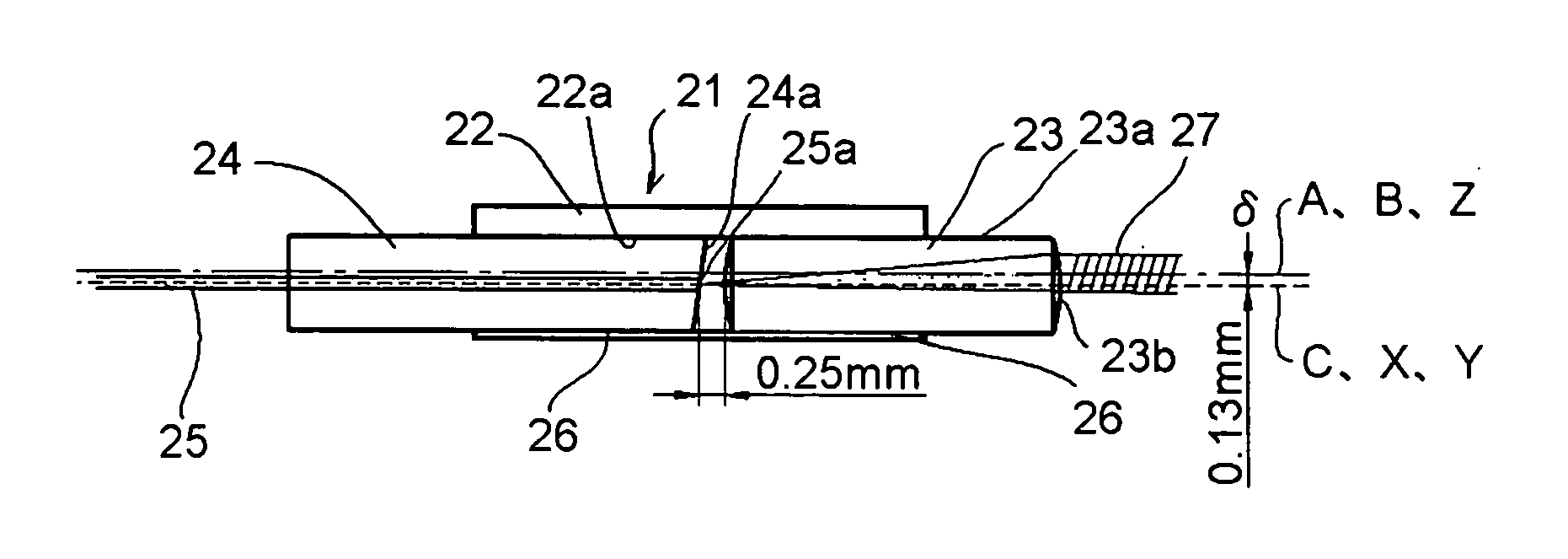
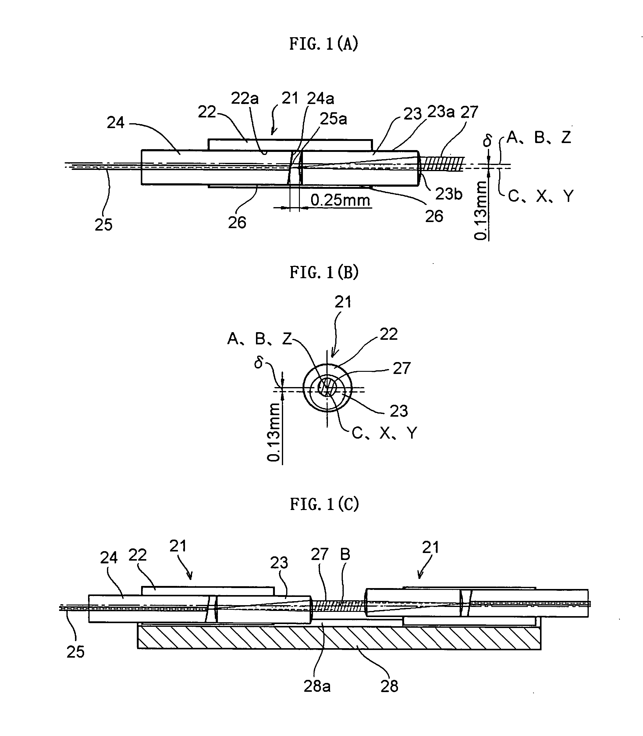
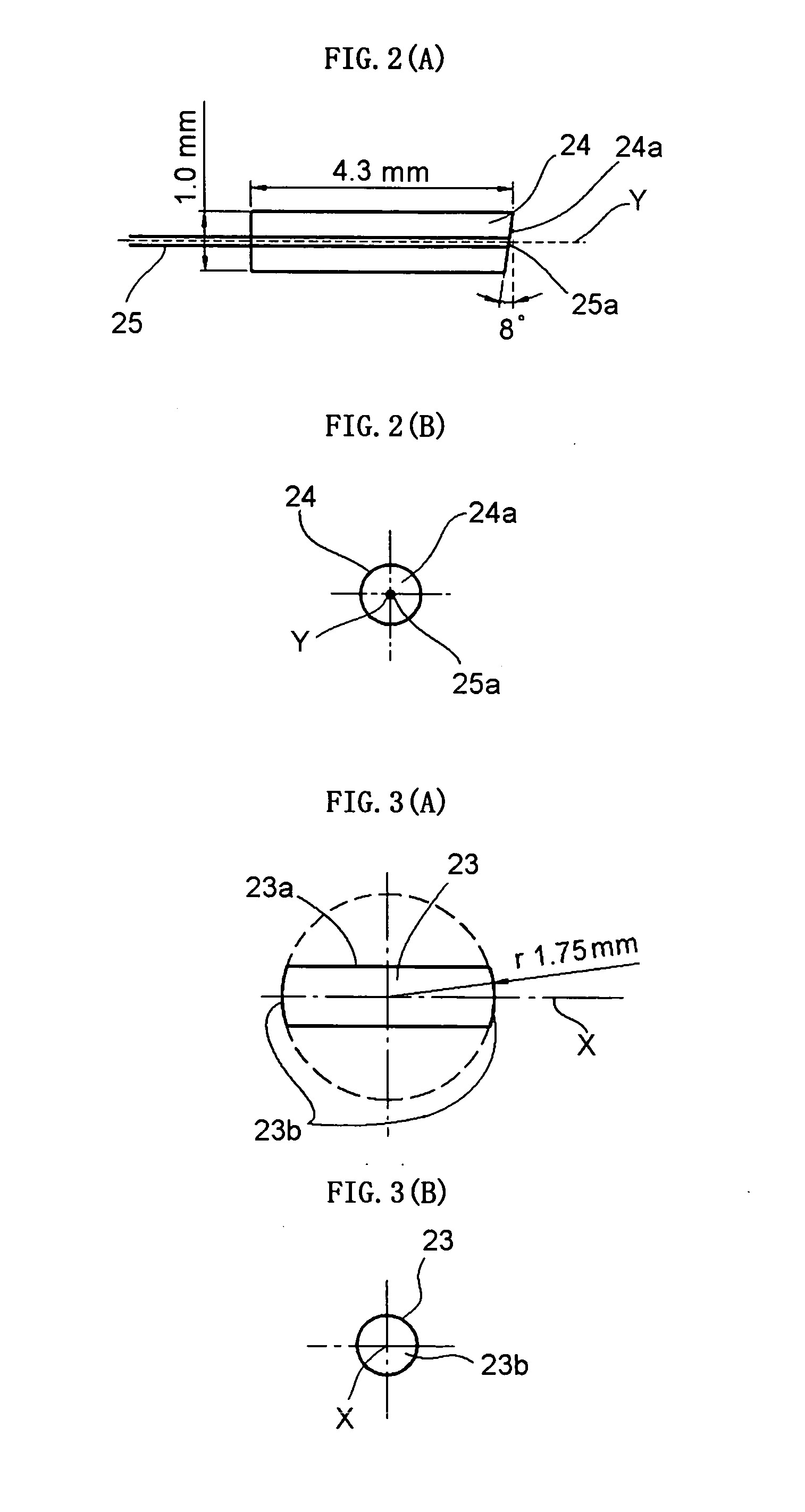
[0062]FIG. 1 is an explanatory diagram of an optical collimator 21 that is an example of the present invention. In the drawing, reference numeral 22 denotes a glass-made eccentric tube serving as an eccentric sleeve; 23, a partially spherical lens; 26, an adhesive; 24, a concentrically structured capillary tube; and 25, an optical fiber.

[0063] When the refractive index of the core portion of the optical fiber 25 is referred to as “n1”, the refractive index of the air in an in-the-atmosphere case is referred to as “n2”, the refractive index of the partially spherical lens 23 is referred to as 37 n3”, the radius of curvature of the partially spherical lens 23 is referred to as “r”, and the angled polished angle of an end face 25a of the optical fiber 25 is referred to as “θ”, an amount δ, by which the eccentric sleeve 22 constituting the optical collimator 21 in FIG. 1 is decentered in advance, is expressed as follows. δ=n32⁢(n3-n2)·r·tan⁡[{arcsin⁡(n1n2⁢sin⁢ ⁢θ)}-θ][Expression⁢ ⁢1]

[...

second embodiment

[0078]FIG. 5 is an explanatory diagram of an optical collimator 31 that is another example of the present invention and has a long working distance. In the drawing, reference numeral 32 denotes a glass-made tube serving as an eccentric sleeve; 33, a partially spherical lens; 36, an adhesive; 34, a capillary tube; and 35, an optical fiber. This example is a case where a glass-made tube is used as the eccentric sleeve 32, but another material may be used instead so long as the mutual differences in coefficient of thermal expansion are 50×10−7 / K or less.

[0079] When the refractive index of the core portion of the optical fiber 35 is referred to as “n1”, the refractive index of the air in an in-the-atmosphere case is referred to as “n2”, the refractive index of the partially spherical lens 33 is referred to as “n3”, the radius of curvature of the partially spherical lens 33 is referred to as “r”, and the angled polished angle of the end face 35a of the optical fiber 35 is referred to as...

third embodiment

[0090]FIG. 6 is an explanatory diagram showing an example of an incremental-type rotary encoder 40 that uses the optical collimator 21 according to the present invention. The rotary encoder 40 is one kind of sensors, which detect rotation angles and rotation angular velocities. In the rotary encoder 40, a scale 41 having signal slits 41a is directly attached to a rotation axis as shown in FIG. 6, and a rotation angle is detected with reference to a pulse signal of collimated beam 27 of the optical collimators 21 passing through the signal slits 41a. It is also possible to detect a rotation angular velocity by differentiating the obtained rotation angle with respect to time.

[0091] With the structure shown in FIG. 6, however, although it is possible to detect the rotation angle, it is impossible to detect a rotation direction. Therefore, in many rotary encoders, the rotation direction is detected and a start point is also detected by using multiple optical collimators 21. By using th...


PUM


Abstract

An optical collimator 21 includes a glass-made partially spherical lens 23 having translucent spherical surfaces 23b with approximately the same center of curvature at both ends of a columnar portion 23a, a glass-made or crystallized glass-made capillary tube 24 holding an optical fiber 25 with an angled end face 25a at a center, and a glass-made or crystallized glass-made cylindrical eccentric sleeve 22 having an inner hole 22a for fixing the partially spherical lens 23 and the capillary tube 24 therein. An optical axis Z of collimated beam 27 is in a round with radius range of 0.02 mm or less, and is in an angle range of 0.2° or less with respect to the center axis B of the outer surface of the eccentric sleeve 22.

Description

TECHNICAL FIELD [0001] The present invention relates to an optical collimator that uses a capillary tube holding an optical fiber for optical communications at a center, a partially spherical lens obtained by working a spherical lens into a columnar shape, and an eccentric sleeve aligning the axes of the optical fiber in the capillary tube and the partially spherical lens with each other. BACKGROUND ART [0002] When a high-speed and large-capacity optical fiber communications system is constructed, many optical devices are used for the system. Some of them include optical devices that extract an optical signal having an arbitrary wavelength from among multiple optical signals, which have multiplexed wavelengths, and optical devices that use an optical crystal for matching phases of optical signals. And many optical collimators are used therein which each convert a widening optical signal emitted from an optical fiber into collimated beam or condense collimated beam onto the optical f...

Claims


Application Information

Patent Timeline
Patent Type & Authority Applications(United States)
IPC IPC(8): G02B27/30G02B6/32G02B6/38
CPCG02B6/3845G02B6/327
Inventor TANAKA, HIROKAZUFUNABIKI, NOBUO
Owner NIPPON ELECTRIC GLASS CO LTD
Why Eureka
Try Eureka