User interface for selection of sampling parameters in a logic analyzer whose data receivers are in groups each having a separate threshold that is common to the channels within each group

Inactive Publication Date: 2006-11-16
AGILENT TECH INC
View PDF2 Cites 7 Cited by
  • Summary
  • Abstract
  • Description
  • Claims
  • Application Information

AI Technical Summary

Benefits of technology

[0027] Logic Analyzers include some singly constrained examples that are of interest. From their beginning, most Logic Analyzers have had probe pods that assist with connecting the signals of interest to the Analyzer. The probe pod might have provision for short flexible ‘flying leads’ with mini-grabbers or push-on sockets on their ends. Flying leads are the do-it-yourself means for c

Problems solved by technology

As the speeds of digital systems increase into the Gigabit per second region the issues of exactly where within the UI to make the threshold decision for a data signal (“delay”), and with what threshold voltage, become increasingly problematic.
And while it is then possible to discern if in that collection of cycles there were instances of overshoot, slow rise or fall times, or inappropriate asserted voltage levels, knowledge about which cycle(s) is(are) at fault is generally lost.
However, this may not actually be an optimum set of sampling parameters.
Particularly so, if the shape of the eye opening for the applied signal is less than ideal.
This sounds harmless enough, but can be difficult to accurately visualize, particularly if the eye diagram for the signal of interest differs significantly from an ideal or nominally correct shape.
It is not so easy to tell by simple observation where the gain in one parameter's margin begins to erode the minimum margin needed for the other.
This last business of signal activity indicated within the nominal eye opening, when combined with different rate of margin consumption versus changes in the sampling parameters, can REALLY complicate the task of finding suitable sampl

Method used


Image

  • User interface for selection of sampling parameters in a logic analyzer whose data receivers are in groups each having a separate threshold that is common to the channels within each group
  • User interface for selection of sampling parameters in a logic analyzer whose data receivers are in groups each having a separate threshold that is common to the channels within each group
  • User interface for selection of sampling parameters in a logic analyzer whose data receivers are in groups each having a separate threshold that is common to the channels within each group

Examples


Example

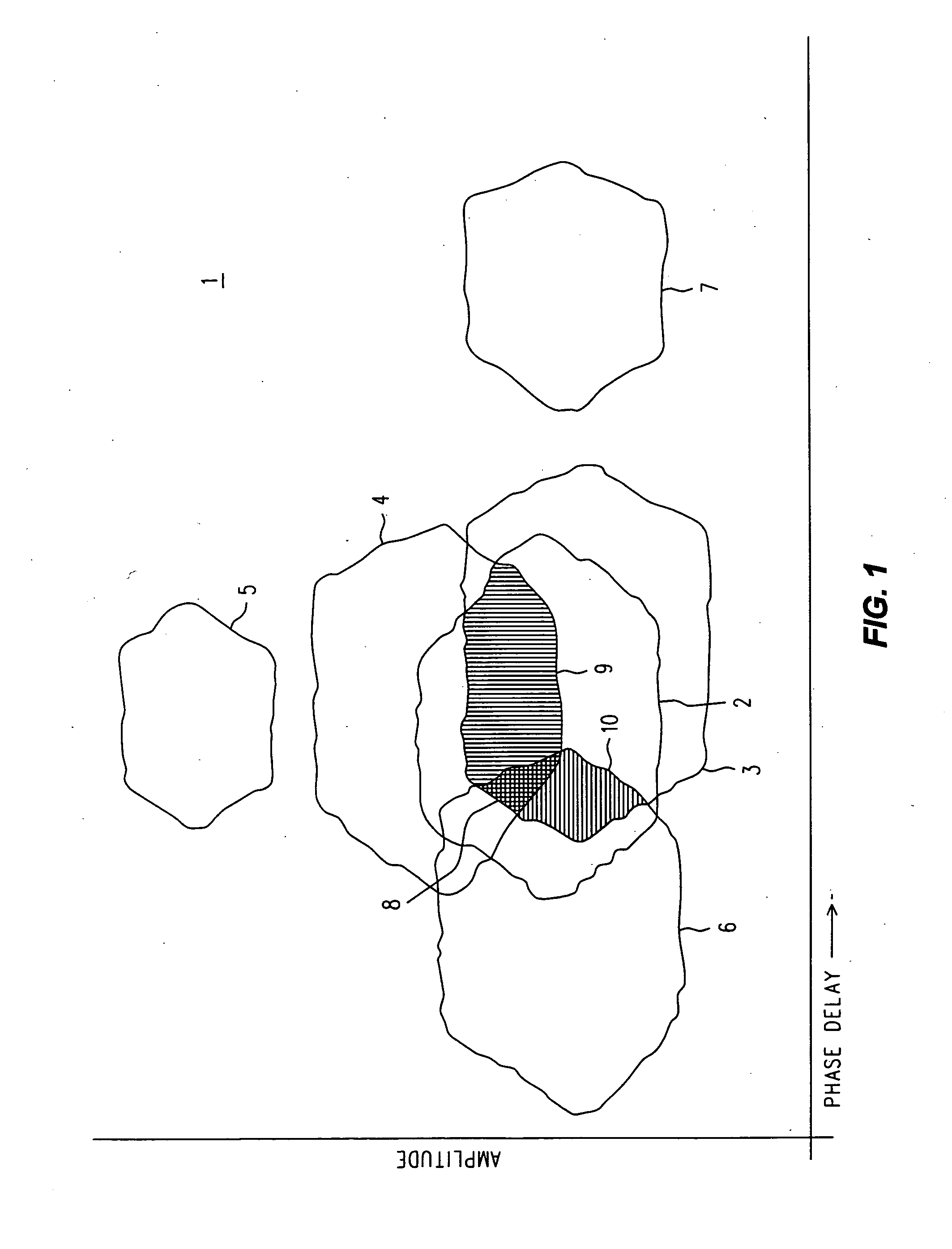
[0053] Refer now to FIG. 1, wherein is shown a simplified representation 1 of a collection of eye diagram eye openings that is a useful point of departure for the discussion that follows. We have suppressed the actual eye diagrams themselves in favor of simply an outline ofthe principal eye openings defined by the bounding traces that are the eye diagrams proper.

[0054] As an aside, we would prefer, although it is not absolutely necessary, that the eye diagrams of interest (from which we shall extract eye openings of interest) be made using a technique that is the same as, or similar to, the one set out in the incorporated “METHOD AND APPARATUS FOR PERFORMING EYE DIAGRAM MEASUREMENTS.” In any event, we do expect that the measured eye diagram data is left in suitable eye diagram data structures so that it may be examined and variously manipulated, after the general fashion described in several ofthe incorporated patent documents. We are not implying that any of the particular manipul...


PUM


Abstract

Eye diagrams are made for signals on each channel in a group thereof. Outlying signals that do not exhibit overlap for a sampling parameter that is to be common for all channels may be ignored and a warning given. Selected, normalized eye openings are used to discover optimum sampling parameters for each channel. Locations within each eye opening are ranked according to preference. Algorithms are used to select a single best value for a sampling parameter common to all the channels, and the corresponding best other sampling parameter is found for each channel. One algorithm disregards good choices for many channels to accommodate any remaining channel by using only a commonly agreed upon value (a jury system). Another algorithm gives weight to a choice according to the number of channels that agree on that choice (majority rule). A graphical user interface facilitates the selection, and emphasizes which sampling parameters are constrained to vary together.

Description

REFERENCES TO INCORPORATED PATENT DOCUMENTS [0001] The subject matter of the present Application pertains generally to the application of eye diagrams to the problem of discovering optimum sampling parameters for a collection of data receivers, and is especially well suited for use with one existing eye diagram measurement technique, although it is by no means limited to use with only that technique. An implementation of that technique is the subject matter of a U.S. Pat. No. 6,785,622 entitled METHOD AND APPARATUS FOR PERFORMING EYE DIAGRAM MEASUREMENTS filed on 29 Oct. 2001 and issued 31 Aug. 2004. An extension of that technique is also of interest, and is described in U.S. Pat. No. 6,810,346 entitled COMPOSITE EYE DIAGRAMS filed 31 Jan. 2002 and issued 26 Oct. 2004. [0002] In addition, three US Patent Applications all filed on 24 Feb. 2005 contain much useful information that is essentially the starting point for the present Application. These three all have, at least at the time...

Claims


Application Information

Patent Timeline
IPC IPC(8): H04B17/00
CPCG01R1/025G01R31/31912G01R31/3171
Inventor NYGAARD, RICHARD A. JR.
Owner AGILENT TECH INC
Why Eureka
Try Eureka