

Digital amplifier system for driving a capacitive load
a digital amplifier and capacitive load technology, applied in the direction of pulse generators, pulse techniques, transmission, etc., can solve the problems of analog systems producing overshoot and ringing, further increasing costs, and increasing system inefficiency, so as to achieve high sampling rate of drive current, reduce weight, volume and cost, and improve control. the effect of accuracy
- Summary
- Abstract
- Description
- Claims
- Application Information
AI Technical Summary
Benefits of technology
Problems solved by technology
Method used
Image

Examples
Embodiment Construction
[0024] Aside from the preferred embodiment or embodiments disclosed below, this invention is capable of other embodiments and of being practiced or being carried out in various ways. Thus, it is to be understood that the invention is not limited in its application to the details of construction and the arrangements of components set forth in the following description or illustrated in the drawings. If only one embodiment is described herein, the claims hereof are not to be limited to that embodiment. Moreover, the claims hereof are not to be read restrictively unless there is clear and convincing evidence manifesting a certain exclusion, restriction, or disclaimer.
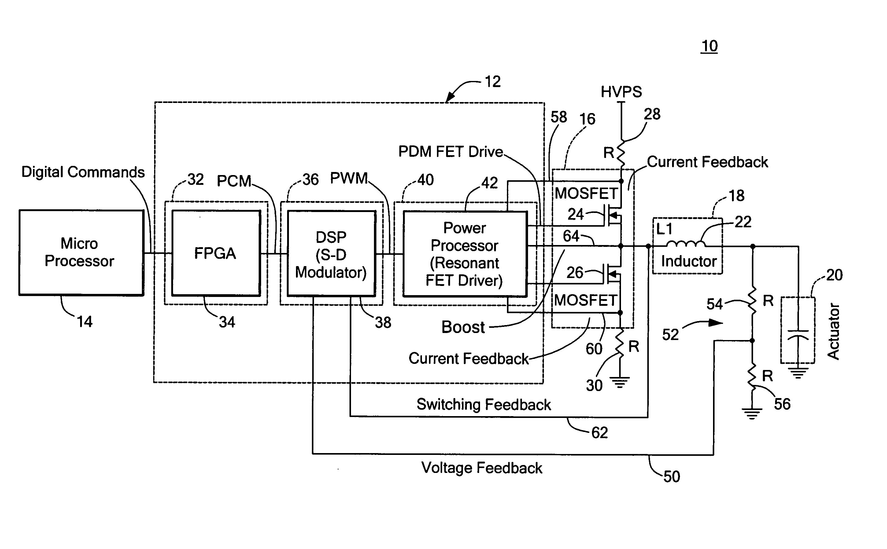
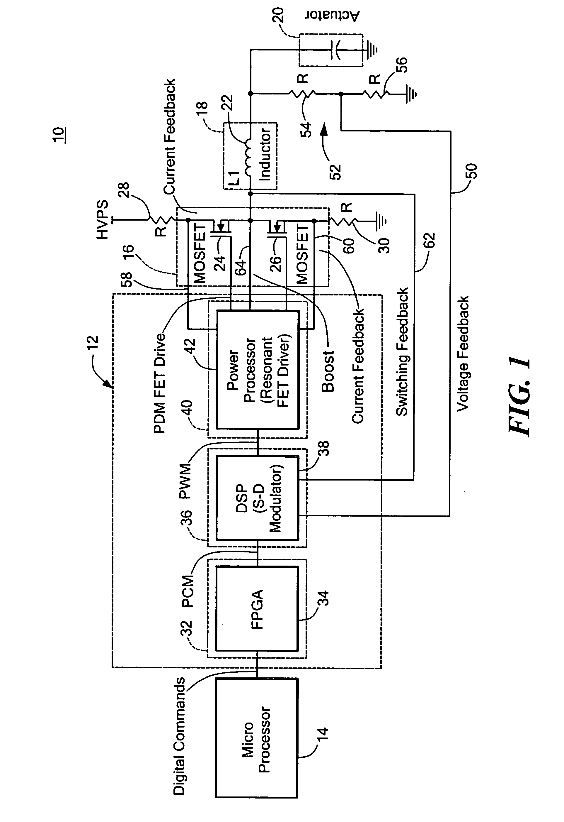
[0025] There is shown in FIG. 1 a digital amplifier system 10 for driving a capacitive load including a digital amplifier controller 12 which is responsive to a digital input command from, for example, a microprocessor 14 to produce a pulse density modulation signal representative of that digital input command to a switch...
PUM
 Abstract
Description
Claims
Application Information