
Helical wind turbine

a wind turbine and helical technology, applied in wind energy generation, motors, sustainable buildings, etc., can solve the problems of obscuring the landscape with the banks of rotating wind turbines, noise concerns, and danger to birds and air traffic, and achieve the effect of efficient capture of wind energy

Inactive Publication Date: 2006-11-16
ARROWIND CORP
View PDF17 Cites 96 Cited by
  • Summary
  • Abstract
  • Description
  • Claims
  • Application Information

AI Technical Summary

Benefits of technology

[0010] Accordingly, it is therefore an object of the present invention to provide a vertical axis wind turbine, which more efficiently enables capture of wind energy than prior art devices.
[0011] It is a further object of the invention to wind turbine design that provides a means to lower the effective weight, and thus the rotation resistance, of a vertical axis wind turbine rotor section section.
[0012] It is a still further object of the present invention to provide a vertical wind turbine design in which the turbulence created in the centre of the wind turbine rotor section, created by a centre axle, is reduced or eliminated.
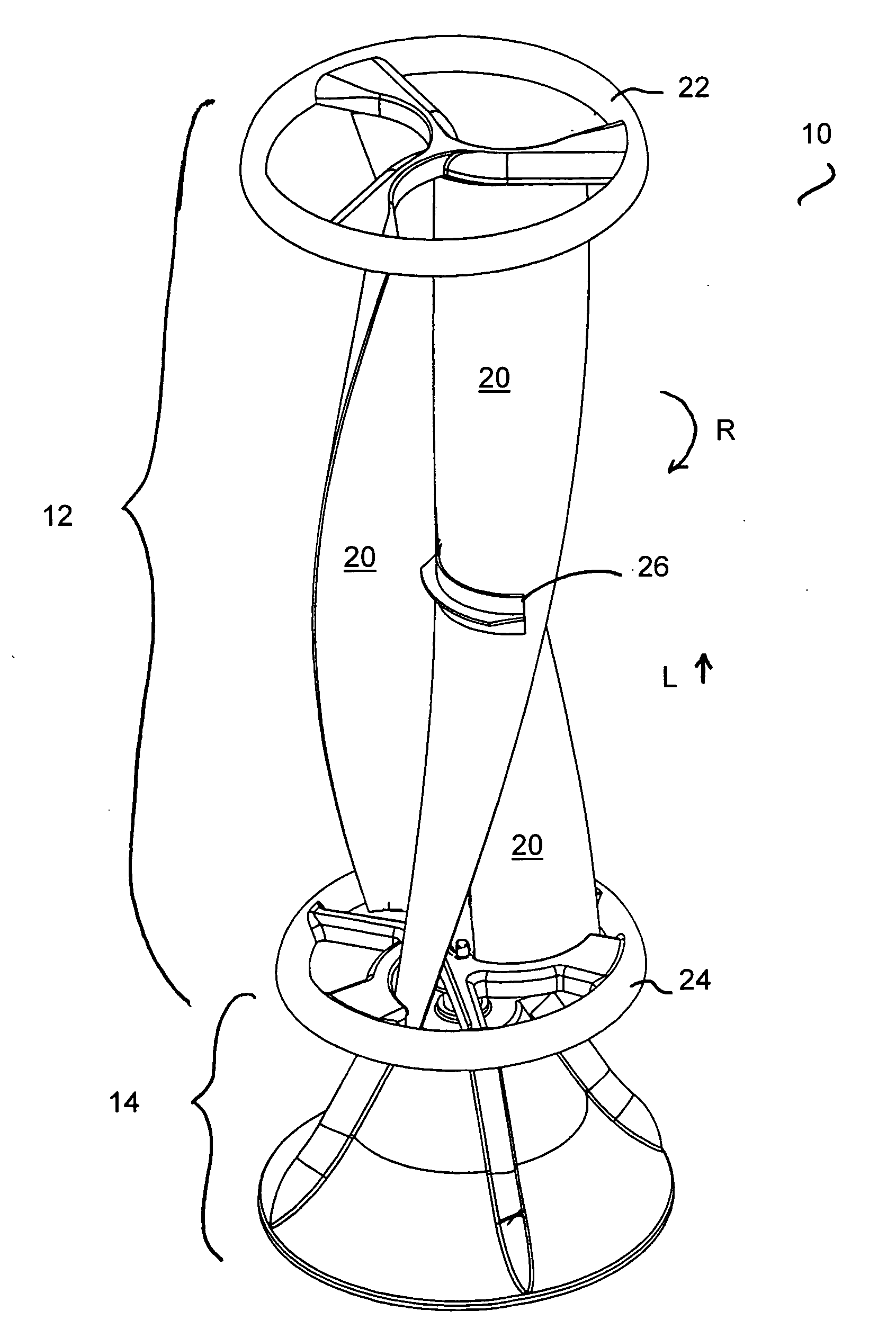
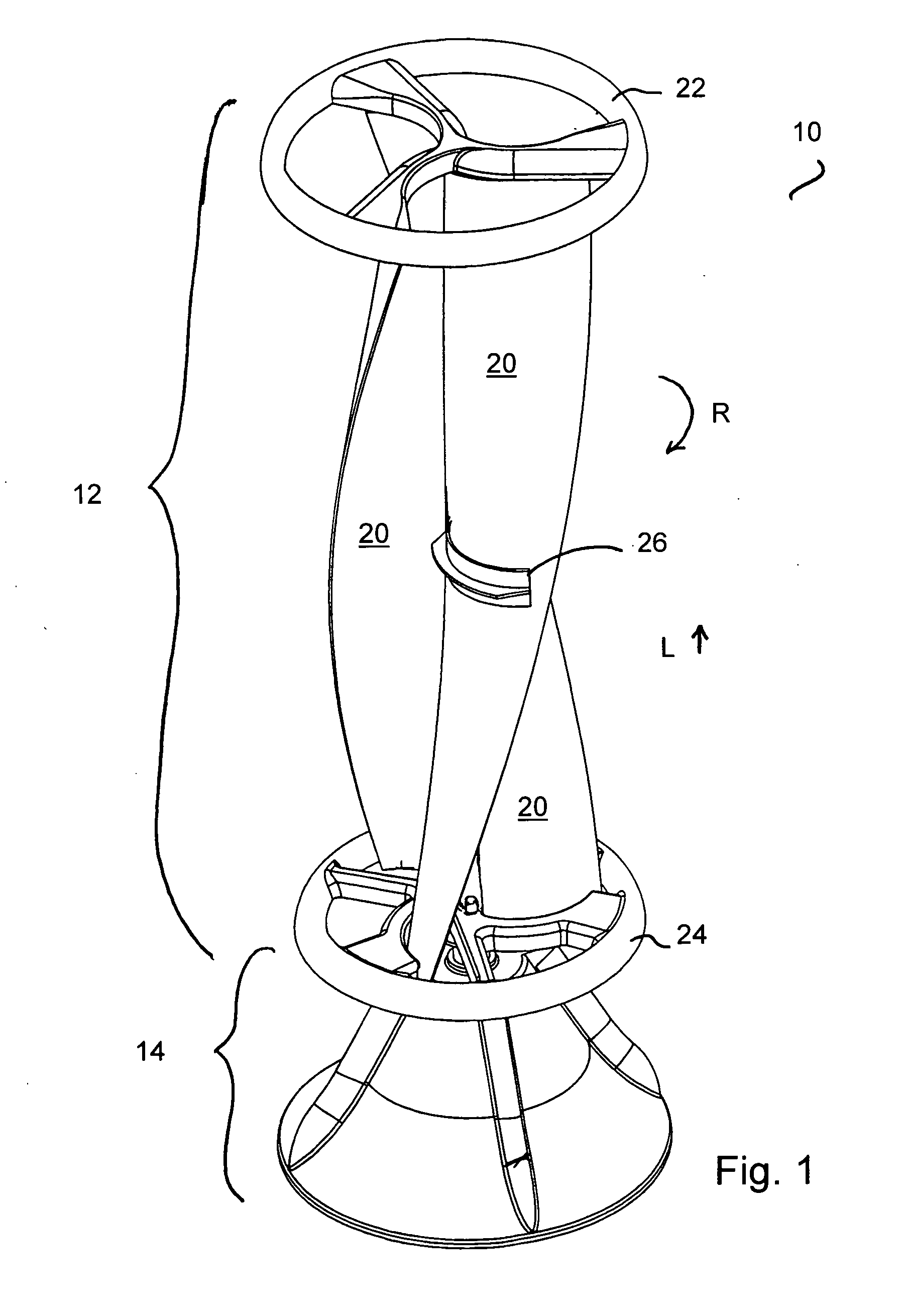
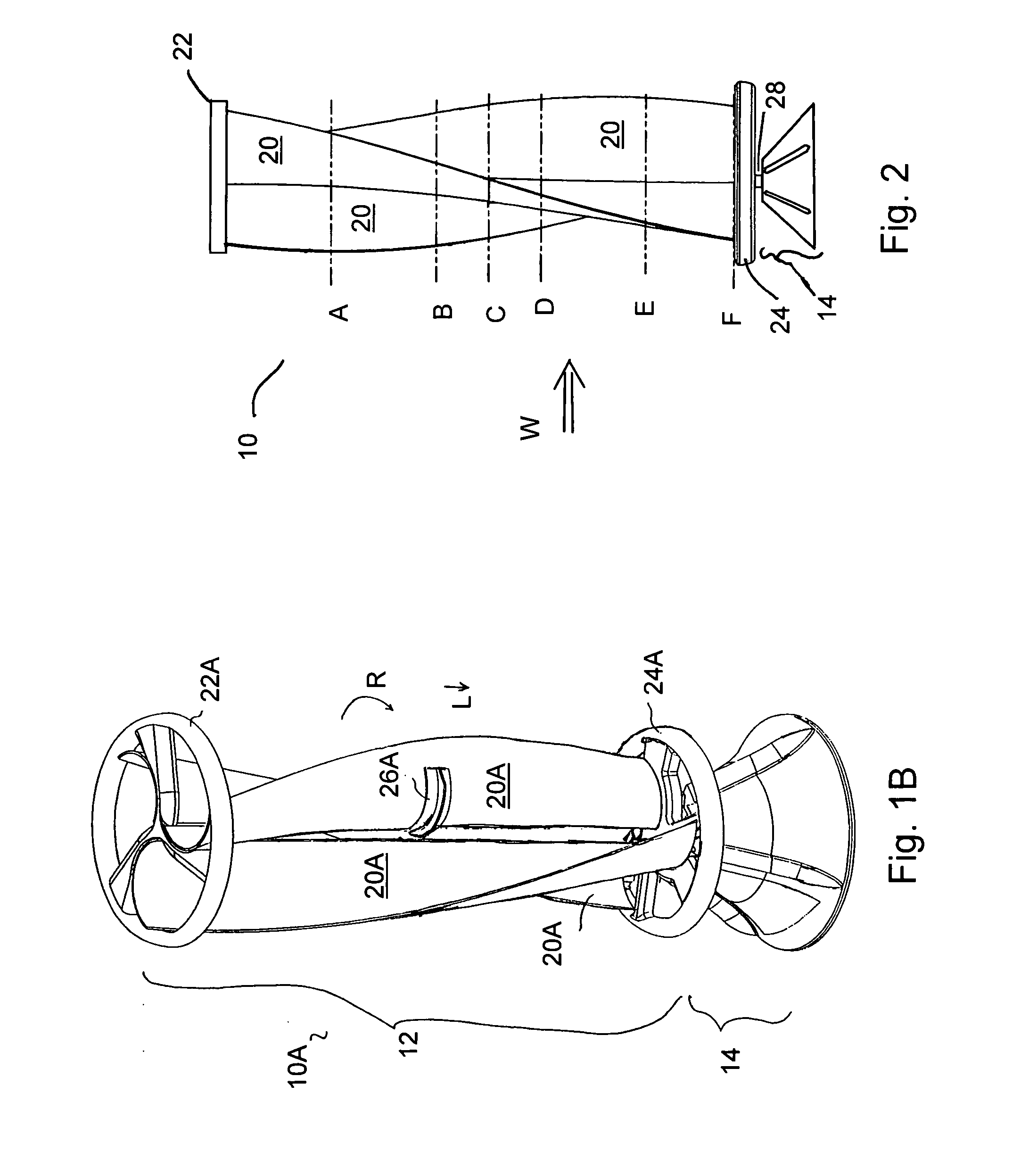
[0017] In a further preferred embodiment, the present invention also provides a vertical axis wind turbine having a central opening between each blade so as to provide a open area along the vertical rotation axis of the rotor section, and thereby eliminate the centre axle found in prior art vertical wind turbine designs.

Problems solved by technology

However, these devices suffer from several disadvantages, including noise concerns, danger to birds and air traffic, obscuring the landscape with banks of rotating windmills due to their large scale design, and in the case of large diameter horizontal axis propellers, having the propellers reach or exceed supersonic speeds at the tips of the rotors.
Also, they are impractical for smaller, owner-controlled applications.
However, this vertical axle creates unnecessary turbulence in the air flow through the wind turbine as the wind passes through the central opening between the blades.
An additional issue in the design of any wind turbine is the need to reduce the rotation resistance, or in some cases, increase the rotation resistance, of the wind turbine rotor section.

Method used


Image

  • Helical wind turbine
  • Helical wind turbine
  • Helical wind turbine

Examples


Embodiment Construction

[0035] The novel features which are believed to be characteristic of the present invention, as to its structure, organization, use and method of operation, together with further objectives and advantages thereof, will be better understood from the following drawings in which a presently preferred embodiment of the invention will now be illustrated by way of example only. In the drawings, like reference numerals depict like elements.

[0036] It is expressly understood, however, that the drawings are for the purpose of illustration and description only and are not intended as a definition of the limits of the invention.

[0037] Also, in the present application, a wind turbine is provided that is intended to be used in the generation of electrical energy as a result of the rotation of the wind turbine. While specific details of the wind turbine will be herein described, the use and conversion of the rotation energy to create electrical energy is believed to be within the scope of the pri...


PUM


Abstract

A vertical axis wind turbine wherein the blades of the rotor section of the wind turbine comprise at least sections wherein the blades have a non-linear configuration in the “z” axis. In a preferred embodiment, the blades of the rotor section have a linear trailing edge with a non-linear, and preferably helical, surface configuration. This particular design allows the blades to provide both a rotational force and a positive or negative lift component. Further, the blades define an open area in the center of the rotor section through which air flow can pass in order to create a vertical vortex of air. As such, a more efficient vertical axis wind turbine provided.

Description

FIELD OF THE INVENTION [0001] The present invention relates to the field of wind turbines, and in particular, relates to vertical axis wind turbines having improved construction features. BACKGROUND OF THE INVENTION [0002] Wind is being increasingly used as a source of energy for driving windmills or wind turbines, in order to generate electrical power. For example, large scale horizontal axis windmills have recently been used extensively to drive electrical generators. However, these devices suffer from several disadvantages, including noise concerns, danger to birds and air traffic, obscuring the landscape with banks of rotating windmills due to their large scale design, and in the case of large diameter horizontal axis propellers, having the propellers reach or exceed supersonic speeds at the tips of the rotors. Also, they are impractical for smaller, owner-controlled applications. [0003] Vertical axis wind turbines are also known and typically have a central vertical rotor secti...

Claims


Application Information

Patent Timeline
Patent Type & Authority Applications(United States)
IPC IPC(8): F03D7/06
CPCF03D3/04F03D3/061F03D3/062F03D3/064F05B2240/12F05B2240/121Y02E10/74F05B2240/213F05B2240/30F05B2240/32F05B2250/25Y02B10/30F05B2240/122Y02E10/728F03D80/00F03D13/20
Inventor NASKALI, PERTTI H.MACLEAN, ANGUSGRAY, NEIL C. C.LEWIS, J. HARRYNEWALL, A. PATRICK
Owner ARROWIND CORP
Learn More