
Multi-band frequency synthesizer

Inactive Publication Date: 2006-11-16
SONY ERICSSON MOBILE COMM AB
View PDF11 Cites 17 Cited by
  • Summary
  • Abstract
  • Description
  • Claims
  • Application Information

AI Technical Summary

Benefits of technology

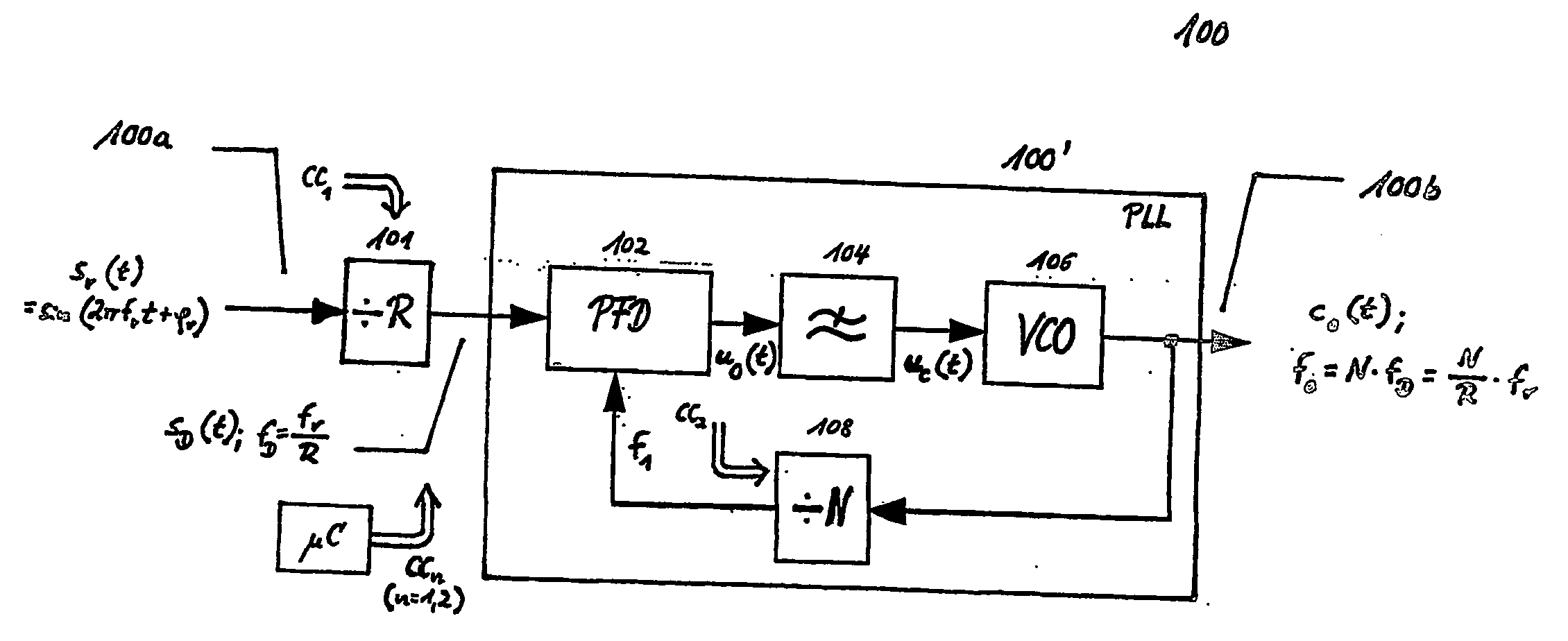
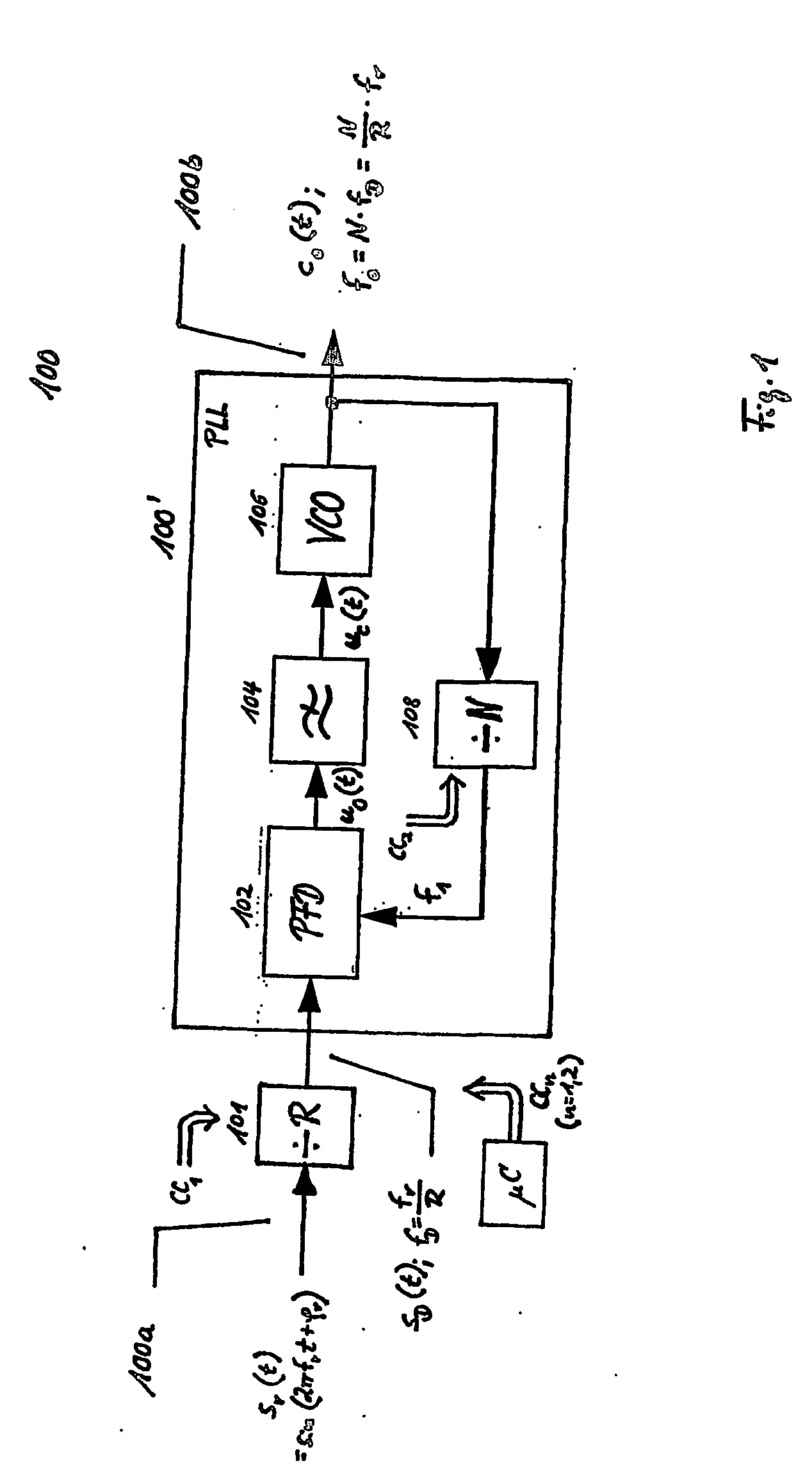
[0018] In view of the above-described state of the art, it is the object of the present invention to provide a cost-effective, energy-saving multi-band frequency synthesizing circuitry with reduced chip-space requirements for generating tunable carrier signals with low phase noise whose carrier frequencies are located in frequency bands which are assigned to the up- and downlink communication channels of the GSM / GPRS 850 MHz, GSM / GPRS 900 MHz, GSM / GPRS (DCS) 1,800 MHz, GSM / GPRS (PCS) 1,900 MHz, and the UMTS standard, respectively.

Problems solved by technology

The disclosed transceiver architecture can not be applied to multi-mode operation, however, because it does not comprise any multi-band frequency synthesizing unit.

Method used


Image

  • Multi-band frequency synthesizer
  • Multi-band frequency synthesizer
  • Multi-band frequency synthesizer

Examples


Embodiment Construction

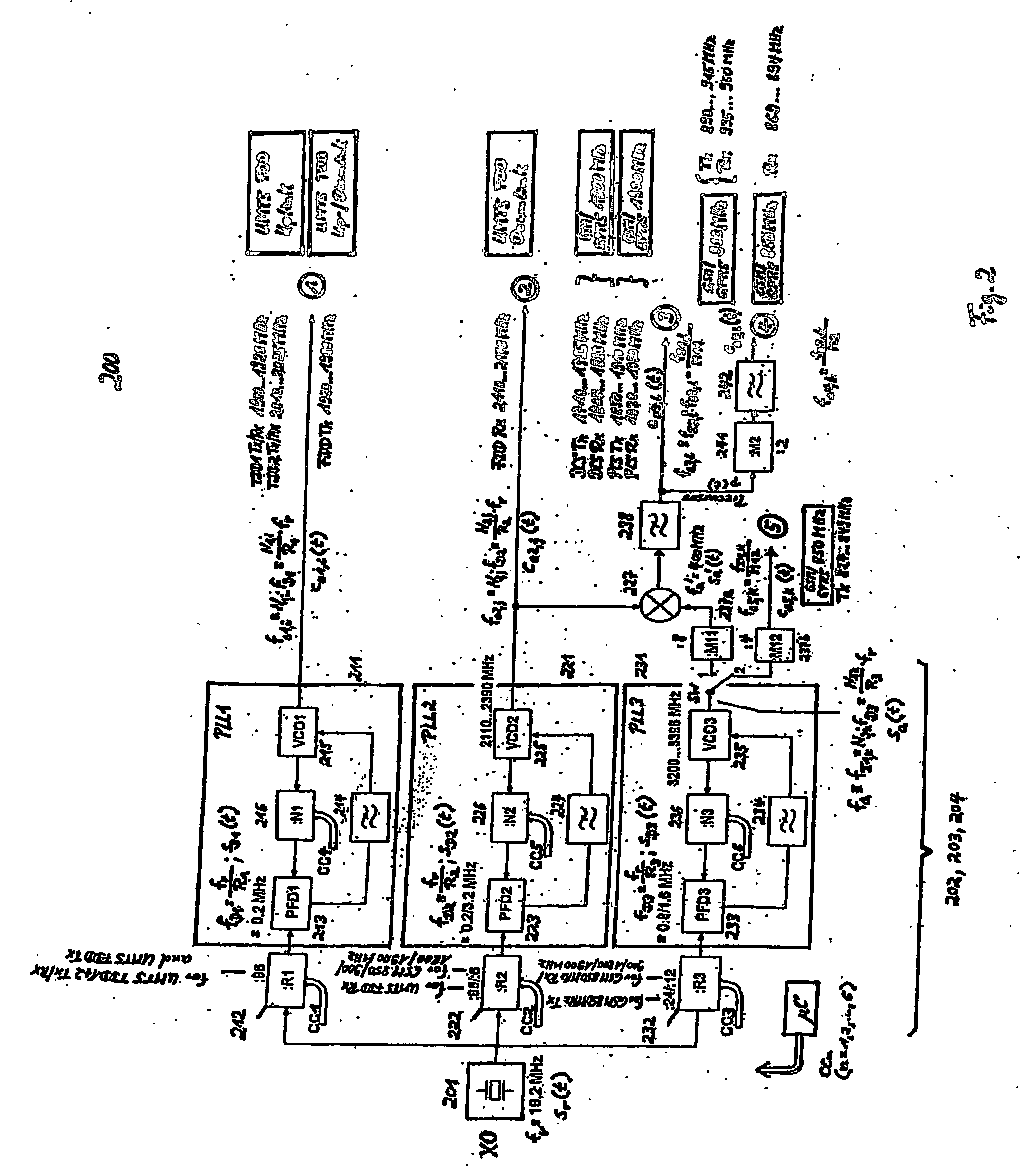
[0026] In the following, one embodiment of the underlying invention as depicted in FIG. 2 shall be explained in detail.

[0027] The embodiment implements a method for operating a multi-band frequency synthesizer 200 of a wireless multi-mode transceiver for generating tunable carrier signals c01,i(t), co2,j(t), co3,l(t), and co4,l(t) whose frequencies fo1,i, fo2,j, fo3,l, and fo4,l are located in different frequency bands and assigned to the up- and downlink channels of a number of wireless communication standards (f.e. GSM / GPRS 900 MHz Tx / Rx, GSM / GPRS (DCS) 1,800 MD Tx / Rx, GSM / GPRS (PCS) 1,900 MHz Tx / Rx, UMTS TDD1 Tx / Rx, UMTS TDD2 Tx / Rx, and UMTS FDD Tx / Rx), respectively. The method comprises the steps of providing (S1) an oscillator signal sr(t) with a constant reference frequency fr of 19.2 MHz, converting (S2) said oscillator signal sr(t) into a first carrier signal co1,i(t) having a frequency fo1,i in the range of a first frequency band (UMTS TDD1+2 Tx / Rx, UMTS FDD Tx), and conve...


PUM


Abstract

A multi-mode PLL frequency synthesizer of a wireless multi-mode transceiver is provided which includes a reference frequency source providing an oscillator signal with a constant reference frequency, a first frequency synthesizer subunit for converting the signal into carrier signals with frequencies in the range of a first frequency band, a second frequency synthesizer subunit for transforming the oscillator signal into carrier signals having frequencies in the range of a second frequency band, and a third frequency synthesizer subunit for converting the oscillator signal into an auxiliary signal with a fixed frequency. The auxiliary signal is used together with the carrier signals of the second frequency band to generate carrier signals with frequencies in the range of a third and fourth frequency band. A frequency divider derives a signal in the range of a fifth frequency band from further intermediate frequency signals supplied by the third frequency synthesizer subunit by dividing the frequency of the auxiliary signal by an integer value.

Description

FIELD AND BACKGROUND OF THE INVENTION [0001] The present invention generally relates to the field of multi-band frequency synthesizer architectures, which can advantageously be applied to wireless multi-mode transceivers in a cellular telecommunication system based on f.e. UMTS or GSM / GPRS technology. It particularly refers to a multi-band frequency synthesizer comprising three frequency synthesizer subunits for generating carrier signals with carrier frequencies suitable f.e. for UMTS and GSM / GPRS bands, especially to an extension of the frequency synthesizer architecture of a conventional quad-band transceiver providing additional carrier signals with appropriate carrier frequencies for the GSM / GPRS 850 MHz frequency band. [0002] The explosion of the wireless communication in the area of cellular telephony and wireless local area networks (LANs) has led to several wireless standards operating at frequencies ranging from 900 to 5,200 MHz. New generation mobile terminals are equippe...

Claims


Application Information

Patent Timeline
IPC IPC(8): H04B1/18H04B1/40
CPCH04B1/406H04B1/005
Inventor PESTRYAKOV, ALEXANDERSMIRNOV, ALEXEJ
Owner SONY ERICSSON MOBILE COMM AB
Learn More