Manufacturing a replication tool, sub-master or replica

Active Publication Date: 2006-11-16
AMS SENSORS SINGAPORE PTE LTD
View PDF74 Cites 40 Cited by
  • Summary
  • Abstract
  • Description
  • Claims
  • Application Information

AI Technical Summary

Benefits of technology

[0006] It is an object of this invention to provide a method of manufacturing a replication tool, a sub-master or a replica in a method of manufacturing micro-optical or micro-mechanical components by replic

Problems solved by technology

Since the replication tools have a limited lifetime, many tooling operations can be required.
Each tooling operation

Method used


Image

  • Manufacturing a replication tool, sub-master or replica
  • Manufacturing a replication tool, sub-master or replica
  • Manufacturing a replication tool, sub-master or replica

Examples


Embodiment Construction

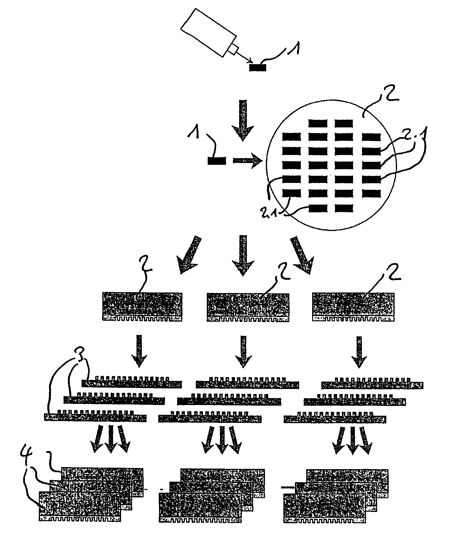
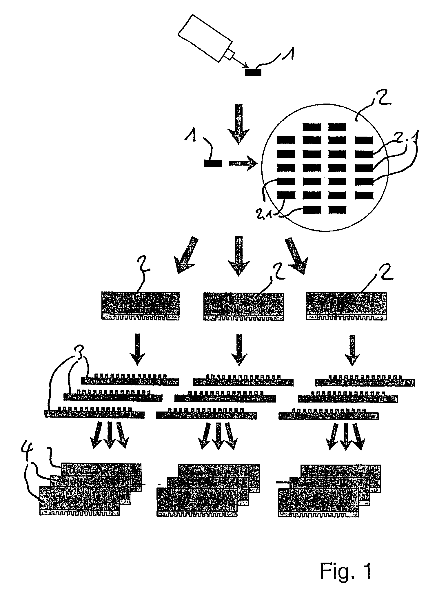
[0061] In this text, ‘replication’ is used for a process of ‘casting’ in a broad sense, i.e. of making a ‘negative’ copy of a structured portion of the element to be replicated. When the resulting element is again replicated, this leads to a ‘positive’ copy of the initially replicated element. In this text, elements that comprise surface parts being a negative copy of portions of the final optical element to be manufactured are called ‘tools’, for example ‘replication tool’ or ‘master tool’. Elements including surface portions with a positive copy of the final element to be manufactured are called ‘master’, ‘sub-master’, or, for the final copy to be diced into the optical elements, ‘final replica’ or ‘replica’.

[0062]FIG. 1 shows an example of a generation process. In a first step, a master 1 is produced by any suitable method. In the figure, a laser beam writing process is symbolized. In a recombination process, to be described in more detail further below, a first generation repli...


PUM

PropertyMeasurementUnit
Thicknessaaaaaaaaaa
Structureaaaaaaaaaa
Areaaaaaaaaaaa

Abstract

The invention concerns a process of manufacturing optical components. A replication tool, a sub-master or a replica is manufactured using a structured element (for example a master) and a substrate. A structure of the structured element is replicated into liquid or plastically deformable material disposed at a first place on said substrate, then hardened to make it dimensionally stable, whereon the structured element is removed. These replicating, hardening and removing steps are repeated for a second, third, etc. place on said substrate the same structured element.

Description

BACKGROUND OF THE INVENTION [0001] 1. Field of the Invention [0002] The present invention is in the field of manufacturing micro-optical, micro-mechanical or micro-fluidic components or elements. It more specifically relates to a method of manufacturing a replication-tool, sub-master or replica. [0003] 2. Description of Related Art [0004] Micro-optical and micro-mechanical components are industrially mass-produced by various technologies, such as injection molding, roller hot embossing, flat-bed hot embossing, UV embossing (all these processes being replication processes) or lithography and etching processes. As an example, in the UV embossing process the surface topology of a master structure is duplicated into a thin film of a UV-curable epoxy resin on top of a substrate. In the case of micro-optics, the surface topology can be a refractive or a diffractive structure, or a combination of both. For that purpose, a tool (negative copy) is prepared from the master, which is then used...

Claims


Application Information

Patent Timeline
IPC IPC(8): G06F15/16B81C99/00G03F7/00
CPCB81C99/0085G03F7/0002B82Y40/00B82Y10/00Y10S425/808
Inventor RUDMANN, HARTMUTMACIOSSEK, ANDREASROSSI, MARKUS
Owner AMS SENSORS SINGAPORE PTE LTD
Why Eureka
Try Eureka