High-performance cutting and turning machine and method for machining particularly spectacle lenses

a cutting and turning machine, high-performance technology, applied in the direction of turning machines, turning machine accessories, lenses, etc., can solve the problems of considerable idle times of the respective machining unit, and achieve the effects of high machining performance, cost-effective, and extremely short time-consuming

Inactive Publication Date: 2006-11-23
SATISLOH GMBH
View PDF16 Cites 19 Cited by
  • Summary
  • Abstract
  • Description
  • Claims
  • Application Information

AI Technical Summary

Benefits of technology

[0006] The object of the present invention is to provide a fully automated high-performance cutting and turning machine which is as cost-effective as possible, and to provide a corresponding method by means of which in particular all the customary plastic spectacle lens materials and all shapes including free-forms and optionally edge machining can be machined in an extremely short time with high machining performance and with high surface precision and quality.
[0007] According to a first aspect of the invention, when machining particularly spectacle lenses as workpieces by means of a machine which comprises at least one cutting unit and at least one turning unit in a common working space, at least two workpieces are machined at the same time in the working space, one of said workpieces being cut while the other is turned. For example, during the pre-machining of one spectacle lens by means of the cutting unit, which can be effected with a high machining performance, another spectacle lens can at the same time be further machined or finished with high surface precision and quality by means of the turning unit. As a result, it is possible to achieve in particular a very high throughput of spectacle lenses, and thus the method according to the invention and the machine according to the invention are particularly suitable for the industrial production of spectacle lenses.
[0008] According to a second aspect of the invention, a machine for machining particularly spectacle lenses as workpieces comprises at least one cutting unit with a machine frame and at least one turning unit with a machine frame, wherein the machine frames of the cutting unit and of the turning unit are essentially decoupled from one another in terms of vibration and delimit a common working space in which the workpieces can be machined at the same time by the cutting unit and the turning unit. The simultaneous cutting and turning machining of spectacle lenses which is thus possible ensures—as already mentioned above—a very high throughput of spectacle lenses (e.g. 140 spectacle lenses per hour). As a result of the fact that, according to the invention, the machine frames are largely decoupled in terms of vibration, surfaces of very high quality can be produced even if there is no downstream polishing process which would further increase the machining time of the individual spectacle lens.
[0009] According to a third aspect of the invention, a machine for machining particularly spectacle lenses as workpieces comprises at least two machining units, each of which comprises at least one tool and a workpiece spindle unit by means of which the workpiece to be machined can be moved in at least one axis direction running transversely to the respective tool, wherein the workpiece spindle units are arranged with respect to one another in such a way that said axis directions are essentially perpendicular to one another. By virtue of this arrangement of the workpiece spindle units, the machine according to the invention is firstly very compact. Secondly, it is possible to position the workpiece spindles with the spectacle lenses held thereon very closely next to one another or above one another, as a result of which an automatic workpiece changeover operation is possible which is very simple and also fast on account of the fact that the workpieces can be changed simultaneously.
[0010] With regard to the greatest possible vibration decoupling, it is preferred if the machine frames of the machining units do not make contact with one another. Continuing the concept of the invention, the machine frames of the machining units may be mounted on a common machine pedestal via vibration decoupling elements. However, it is in principle also conceivable that just one of the machine frames is mounted on the common machine pedestal via vibration decoupling elements, while the other machine frame is attached directly to the machine pedestal. The vibration decoupling elements are preferably commercially available air spring elements. For good vibration behaviour of the machine, it is furthermore advantageous if the machine frames of the machining units are made of polymer concrete, which provides a good damping effect.

Problems solved by technology

However, these were individual machines with separate working spaces, which were in each case loaded by means of separate loading devices and which in turn required additional devices for transferring the workpieces from one machining operation to the next.
During the cutting operation, the turning part of the machine was not used or was unable to be used, and on the other hand, during the turning operation, the cutting part was not used or was unable to be used, so that there were considerable idle times for the respective machining unit.

Method used


Image

  • High-performance cutting and turning machine and method for machining particularly spectacle lenses
  • High-performance cutting and turning machine and method for machining particularly spectacle lenses
  • High-performance cutting and turning machine and method for machining particularly spectacle lenses

Examples


Embodiment Construction

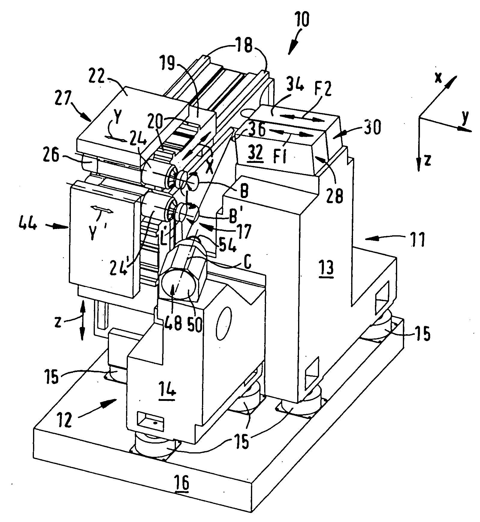
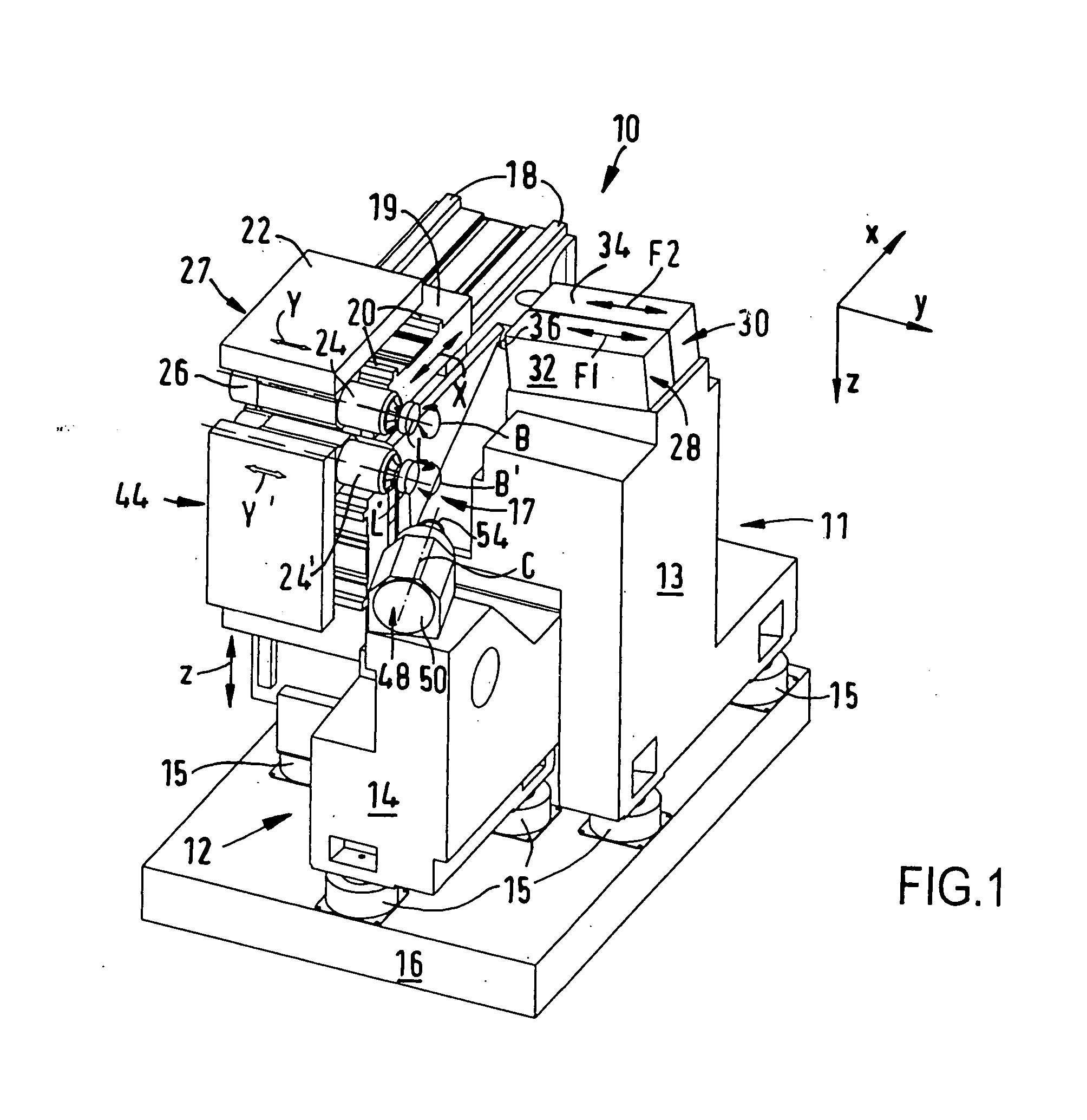
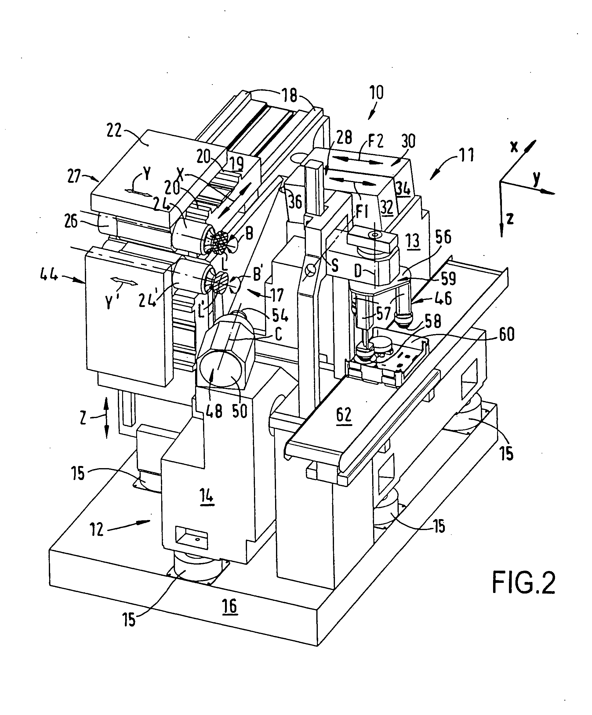
[0024] FIGS. 1 to 11 show in a partially schematic manner a CNC-controlled high-performance cutting and turning machine 10 for machining spectacle lenses L made of plastic in a right-angled Cartesian co-ordinate system, in which the small letters x, y and z respectively denote the width direction (x), the length direction (y) and the height direction (z) of the machine 10. The casings and protective devices of the machine 10 have been omitted in the figures for the sake of clarity.

[0025] According to FIGS. 1 to 5, the machine 10 comprises a turning unit which is referenced 11 as a whole and a cutting unit which is referenced 12 as a whole, which are isolated from one another in terms of vibration. The turning unit 11 comprises a first machine frame 13 which is made of polymer concrete, while the cutting unit 12 comprises a second machine frame 14 which is also made of polymer concrete. The first machine frame 13 and the second machine frame 14, which do not make contact with one an...


PUM

PropertyMeasurementUnit
angleaaaaaaaaaa
angleaaaaaaaaaa
distancesaaaaaaaaaa

Abstract

A method for machining particularly spectacle lenses by means of a machine which comprises at least one cutting unit and at least one turning unit in a common working space, wherein at least two spectacle lenses are machined at the same time in the working space, one of said spectacle lenses being cut while the other is turned. The machine frames of the cutting unit and of the turning unit are essentially decoupled from one another in terms of vibration and / or at least two machining units of the machine comprise workpiece spindle units for generating a transverse movement of the spectacle lens to be machined with respect to the respective tool, the workpiece spindle units being arranged essentially perpendicular to one another. As a result, it is possible for spectacle lenses to be machined in an extremely short time with high machining performance and with high surface precision and quality.

Description

TECHNICAL FIELD [0001] The present invention relates to a high-performance cutting and turning machine and to a corresponding method for machining particularly spectacle lenses. The invention relates specifically to the industrial machining of prescription surfaces of spectacle lenses made of plastics, such as polycarbonate, CR39 and so-called “High Index” materials. PRIOR ART [0002] In the machining of plastic spectacle lenses, a spectacle lens blank is usually provided which is injection-molded from plastic and has a standardised, finished convex outer surface with a spherical or progressive shape for example. The inner surface or prescription surface, which is usually concave, is given a spherical, aspherical, toric, atoric, progressive or free-form geometry (e.g. progressive surfaces) by means of a machining operation to remove material, depending on the desired optical effect. The typical conventional procedure during the machining of inner surfaces provides that, once the spec...

Claims


Application Information

Patent Timeline
Patent Type & Authority Applications(United States)
IPC IPC(8): B23B3/00B23B5/00
CPCB23Q1/015Y10T82/2524B24B13/0037B24B27/0076B24B41/005B24B41/007Y10T409/304312Y10T82/2566Y10T29/49995Y10T82/10Y10T29/5114Y10T82/2514Y10T409/303808Y10T409/305712Y10T409/309576Y10T82/2595B23Q39/04
Inventor FIEDLER, UDOHANISCH, MANFREDTROSS, KARL-HEINZWALLENDORF, STEFFENSCHAEFER, HOLGER
Owner SATISLOH GMBH
Why Eureka
Try Eureka