Low range bonding tool

a low-range, tool technology, applied in the direction of semiconductor devices, cooking-vessel materials, kitchen equipment, etc., can solve problems such as failure of integrated circuits

Inactive Publication Date: 2006-11-23
REIBER STEVEN F
View PDF97 Cites 9 Cited by
  • Summary
  • Abstract
  • Description
  • Claims
  • Application Information

AI Technical Summary

Benefits of technology

[0014] In accordance with an embodiment of the present invention, the range of resistance needs to be lower as the electrostatic discharge (ESD) voltages get smaller to avoid damaging delicate electronic devices by any electrostatic discharge. A bonding tool tip or wedge bonding tool must conduct electricity at a rate sufficient to prevent charge buildup and stop all transient currents, but not at so high a rate as to trap voltage in the device being bonded. It is desirable for the bonding tool tip or wedge bonding tool to discharge as quickly as possible but to have less than 5 milliamps of currents. The tool tip or wedge bonding tool should also discharge or block any sudden surges of current that could damage the part being bonded.
[0018] In a second embodiment, tools maybe made by forming a thin layer of a highly doped semiconductor on an insulating core. In this instance, the core provides mechanical stiffness while the semi-conductor surface layer provides abrasion resistance and provides a charge carrier path from the tip to mount that will permit dissipation of electrostatic charge at an acceptable rate; for example, a diamond tip wedge that is ion implanted with boron.

Problems solved by technology

This could present a problem as a one-volt static discharge could generate a 20 milliamp current to flow, which could cause the integrated circuit to fail due to this unwanted current.

Method used


Image

  • Low range bonding tool
  • Low range bonding tool
  • Low range bonding tool

Examples


Embodiment Construction

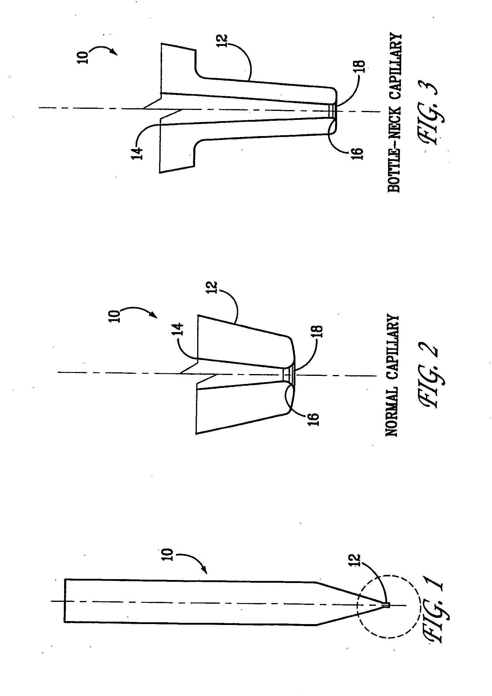
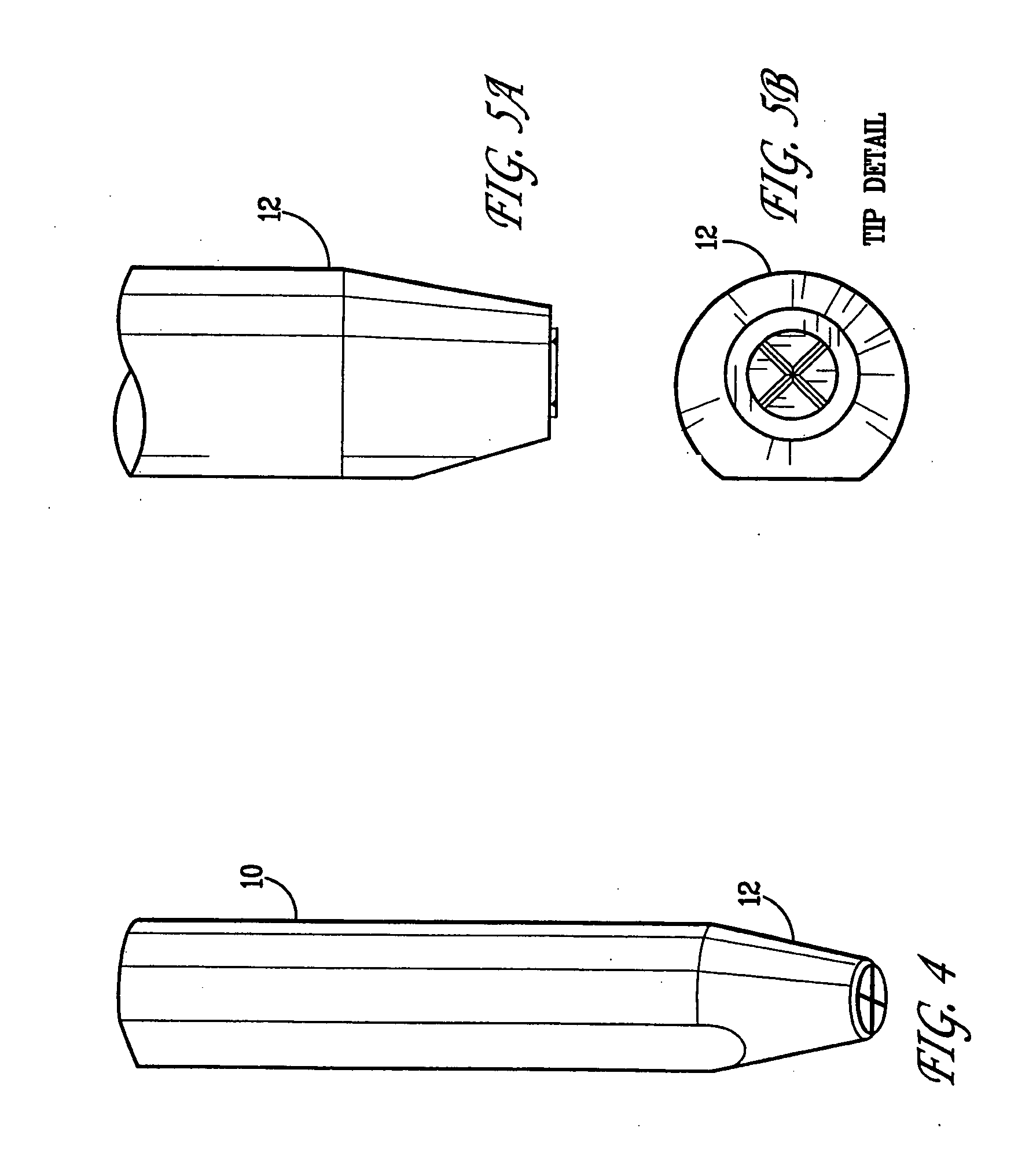
[0029]FIG. 1 illustrates an exemplary capillary bonding tool 10. In one embodiment, the bonding tool 10 is about one-half inch (12-13 mm) long and about one-sixteenth inch (1.6 mm) in diameter. A bonding tool tip 12 is, in exemplary embodiments, 3 to 10 mils (0.08 to 0.25 mm) long. Running a length of the bonding tool 10 but not viewable in FIG. 1, is a tube hole, which will accommodate a continuously fed length of gold wire (not shown).

[0030]FIG. 2 is an enlarged, cross-sectional view of the capillary bonding tool 10 of FIG. 1. Only that portion of the bonding tool 10 shown within the dotted circle in FIG. 1 is shown in FIG. 2. Tool tip 12 has the tube hole 14, which may run the entire length of bonding tool 10. Exit hole 18 is where the wire (not shown) exits tool tip 12. If a ball is formed on the wire, the ball will be seen immediately adjacent the exit hole 18. A chamfer surface 16, at the exit hole 18, accommodates the ball that has been formed at the end of the gold wire. Th...


PUM


Abstract

Bonding tool tips and wedge tools for bonding electrical connections are disclosed herein. The tool tips have 102 to 105 ohms of resistance and the wedge bonding tools have a range of 1012 to 1019 ohms of resistance. A resistive material coating the tool tip and wedge tool has a resistance low enough to discharge a voltage in a device being bonded and high enough to avoid current flow large enough to damage the device being bonded.

Description

CROSS-REFERENCE TO RELATED APPLICATIONS [0001] This application is a continuation-in-part and claims the priority benefit of U.S. patent application Ser. No. 10 / 943,151 filed Sep. 15, 2004 and entitled “Bonding Tool with Resistance,” which claims the priority benefit of U.S. provisional patent application No. 60 / 503,267 filed Sep. 15, 2003 and entitled “Bonding Tool” and is also a continuation-in-part and claims the priority benefit of U.S. patent application Ser. No. 10 / 650,169 filed Aug. 27, 2003 and entitled “Dissipative Ceramic Bonding Tool Tip,” which is a continuation of U.S. patent application Ser. No. 10 / 036,579 filed Dec. 31, 2001 and entitled “Dissipative Ceramic Bonding Tool Tip,” which claims the priority benefit of U.S. provisional patent application No. 60 / 288,203 filed May 1, 2001 and is also a continuation-in-part and claims the priority benefit of U.S. patent application Ser. No. 09 / 514,454 filed Feb. 25, 2000 and entitled “Dissipative Ceramic Bonding Tool Tip,” whi...

Claims


Application Information

Patent Timeline
IPC IPC(8): A47J36/02
CPCH01L24/45H01L24/78H01L2924/01033H01L2924/01006H01L2924/00014H01L2924/14H01L2924/04941H01L2924/01105H01L24/85H01L2224/45144H01L2224/78302H01L2224/85205H01L2924/01005H01L2924/01013H01L2924/01014H01L2924/01027H01L2924/0104H01L2924/01074H01L2924/01075H01L2924/01078H01L2924/01079H01L2924/01082H01L2224/48H01L2924/00H01L2924/00015
Inventor REIBER, STEVEN F.
Owner REIBER STEVEN F
Why Eureka
Try Eureka