Each of the above methods, however, suffers from certain inherent disadvantages, which renders it unsuitable or unsatisfactory for the economical production of finely patterned multicolored rings and other decorative metal objects, particularly objects such as wedding bands wherein the bonds between different metals must be strong enough to hold up to stretching and
sizing as well as withstand decades of wear.
Aesthetically these methods are also inferior in regards to producing a pattern with flowing, natural looking, or woodgrain patterns.
The traditional methods employed to create Mokume Gane and Damascus Steel cannot efficiently be utilized in a factory setting.
Although these methods are capable of yielding very beautiful and finely patterned material, the knowledge, judgment, skill, and experience required to create this material is quite extensive and far beyond the expertise of factory workers.
Additionally, because the material must be hand wrought, inconsistency of patterning and material integrity is quite common.
Another drawback of material formed by other methods such as U.S. Pat. No. 3,465,419, U.S. Pat. No. 4,927,070, U.S. Pat. No. 4,399,611, U.S. Pat. No. 5,815,790, and U.S. Pat. No. 6,857,558 is that all are necessarily formed into, or utilize flat billets.
If it ever becomes necessary to re-size the wedding ring, the seam is vulnerable to breakage and its presence restricts the methods by which the ring may be successfully sized, making the whole process more labor intensive and expensive.
This is quite an inefficient use of the material, and when, in the case of wedding rings, the materials are precious metals, is cost prohibitive.
Secondly, options for creating interesting patterns in thick billets of material that are large enough from which to
machine rings, are severely limited, being simple variations of flat laminates.
The inlay process previously outlined is labor intensive, and requires skilled artisans trained in the method.
These techniques are also beyond the skills of most factory workers and do not lend themselves to high volume production.
In addition, soldered or hammer inlay techniques do not create a true metallurgical bond, so that the bonds created between the inlay and the
base metal with these methods are forever vulnerable to separation.
This creates many problems if the material has to be altered in shape, or forged, and in the case of wedding rings, makes
sizing difficult and expensive.
Lastly, inlay techniques by their very nature are quite coarse and cannot produce the fine sort of patterning possible by other methods.
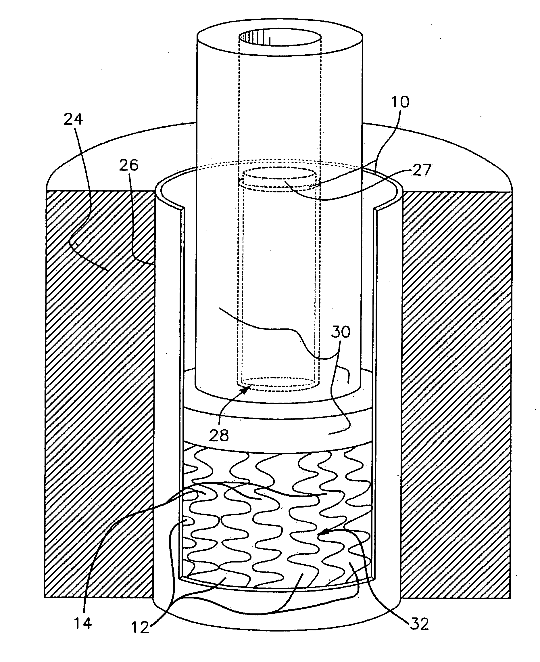
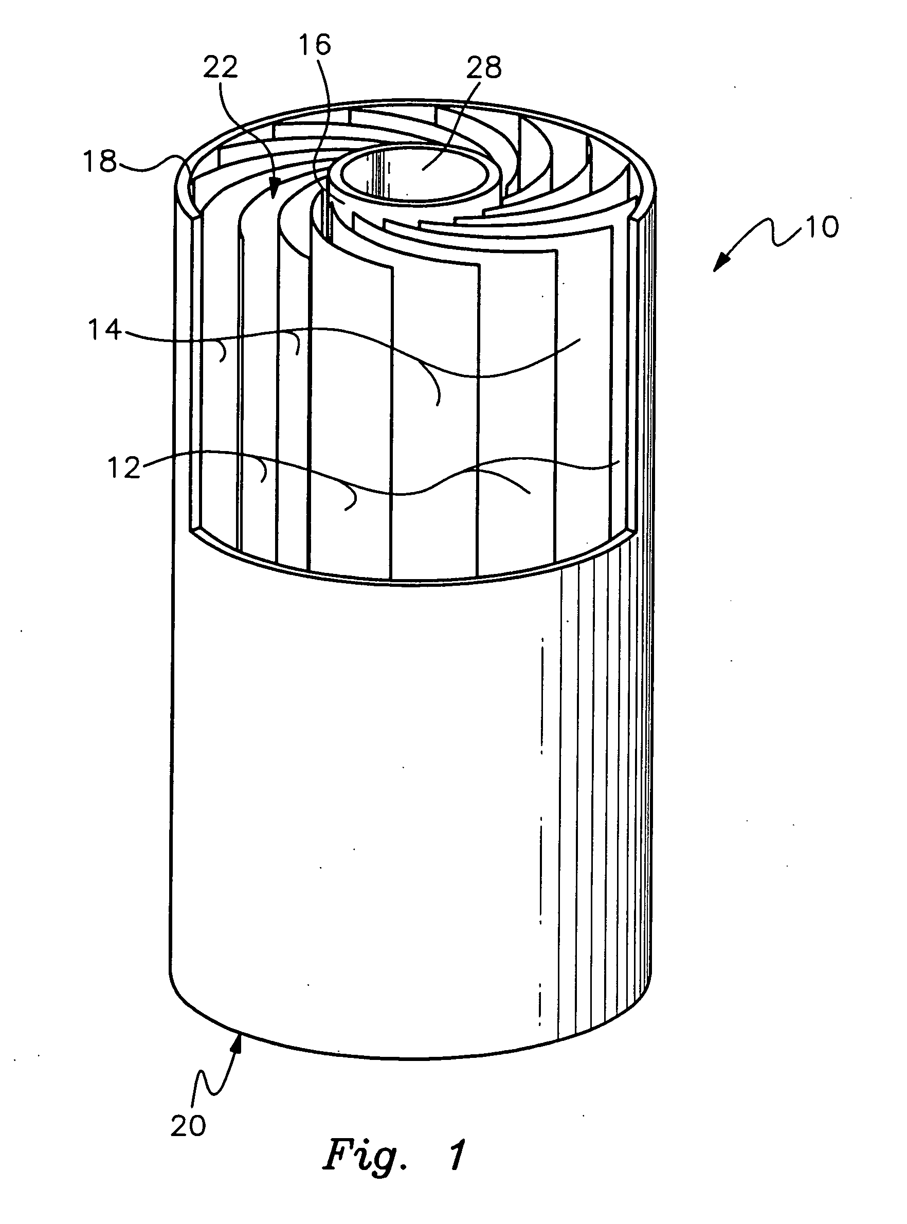
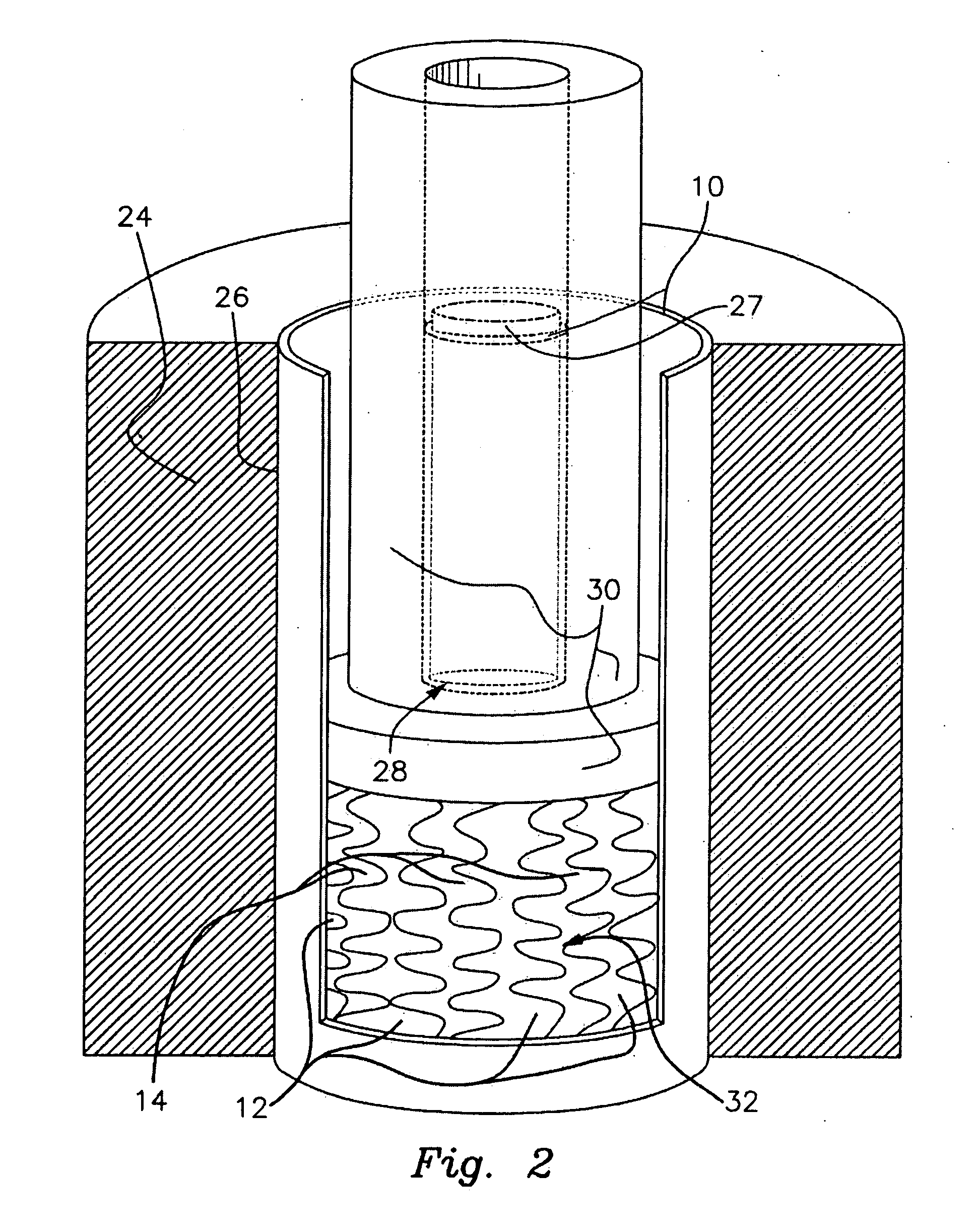
The method utilizing concentric nested tubing (U.S. Pat. No. 4,114,398 and others) also has severe limitations.
Because the tubing is axially straight walled, with the few
layers of the composite tubing
lying parallel to one another, patterning options are very limited and are, in a factory setting, constrained to cuts performed on a lathe or milling
machine.
This creates a simple pattern, but it is neither fine, nor does it yield a product where the design is flush to the
smooth surface of the overall form.
While this method can effectively mimic the appearance of difficult to produce metal
overlay techniques, it is not suited for producing either fine or interesting patterns flush to the surface of a wedding ring, or other jewelry object.
Also, because the cross sectional thickness of wedding bands made by this process varies widely, altering the
finger size of these rings by conventional methods of stretching and rolling can be difficult.
The double
casting method is also quite limited.
The production of fine patterns in the
base metal by
casting is very difficult due to the delicateness required from both the
wax models, and the metal castings.
Also, the great variation in the thicknesses within the
base metal piece, make
casting these shapes difficult.
Machining,
etching, and
stamping may also be used to create the cavities into which the inlay metal may be cast, but these methods are not capable of producing fine patterning of any substantive depth.
This method also achieves no metallurgical bonding, and therefore the metal
layers are prone to separate when any stress is applied to the object.
While this method is superior to double casting in the sense that the inlay can achieve a
diffusion bond with the cast or machined base, these bonds are still fragile and vulnerable to breaking in subsequent forming operations such as
forging, rolling, or
sizing.
