Chemical diffusion system, chemical diffusion apparatus, chemical diffusion unit and chemical cartridge

a chemical diffusion and chemical technology, applied in lighting and heating apparatuses, tobacco, combustion types, etc., can solve the problems of time-consuming installation operation, chemical such as a sex pheromone cannot be effectively diffused in the method of natural diffusion, and the chemical is not easily dispersed effectively. achieve the effect of high efficiency

Inactive Publication Date: 2006-11-23
SEIKO EPSON CORP
View PDF6 Cites 39 Cited by
  • Summary
  • Abstract
  • Description
  • Claims
  • Application Information

AI Technical Summary

Benefits of technology

[0049] Moreover, changeably mounting at least one of the chemical reservoir part, the diffusing means, the chemical supply tube and the pressurized gas reservoir part to the chemical cartridge allows them to be individually changed.
[0050] In order to diffuse a chemical in a target place or in a wide area with on

Problems solved by technology

This causes much unnecessary diffusion of a chemical since the diffusion amount is more in the daytime when the temperature is high.
Accordingly, a chemical such as a sex pheromone cannot be effectively diffused in the method of natural diffusion.
This causes a problem that an installing operation becomes time-consuming since a large number of dispensers should be installed generally.
In addition, there is a problem that a conventional natural diffusion type dispenser of the throwaway-type, and thus, uneconomical.
Accordingly, the conventional chemical diffusion apparatus cannot optimally diffuse a chemical in accordance with a pattern of behavior of a noxious insect subject to extermination, weather, or a place of installing the chemical diffusion apparatus.
Accordingly, a change in place of installation and chemical cannot be easily performed.
From such a point of view, it is also known that changing a chemical is not ea

Method used


Image

  • Chemical diffusion system, chemical diffusion apparatus, chemical diffusion unit and chemical cartridge
  • Chemical diffusion system, chemical diffusion apparatus, chemical diffusion unit and chemical cartridge
  • Chemical diffusion system, chemical diffusion apparatus, chemical diffusion unit and chemical cartridge

Examples


embodiment 1

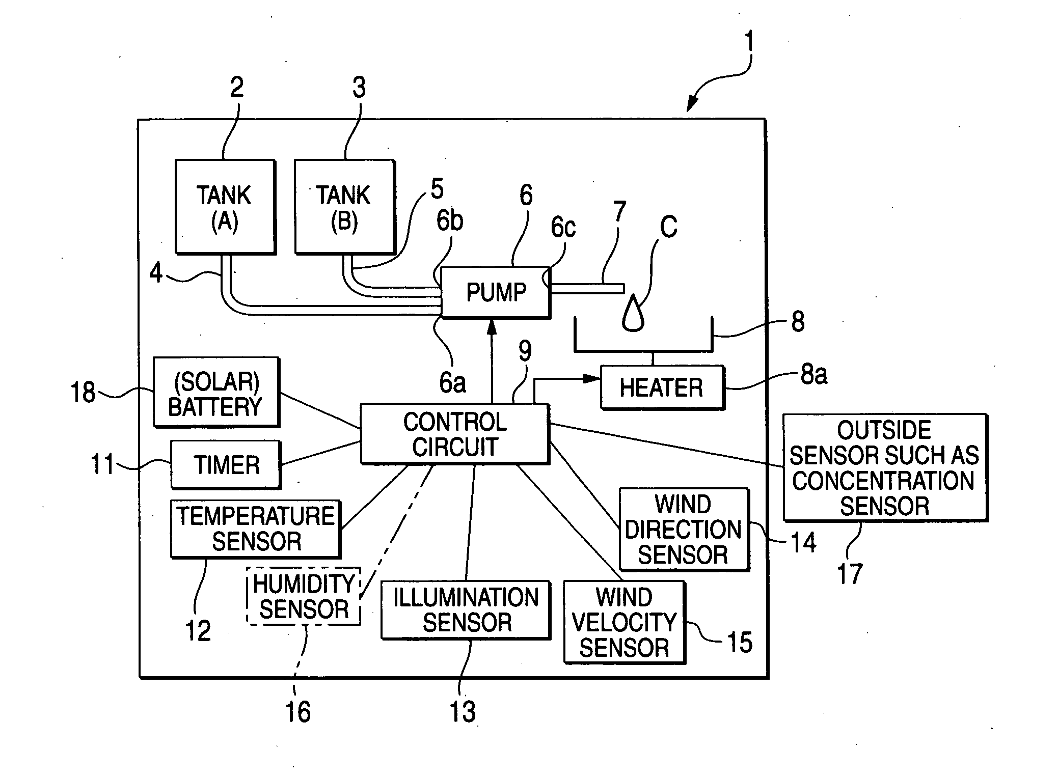
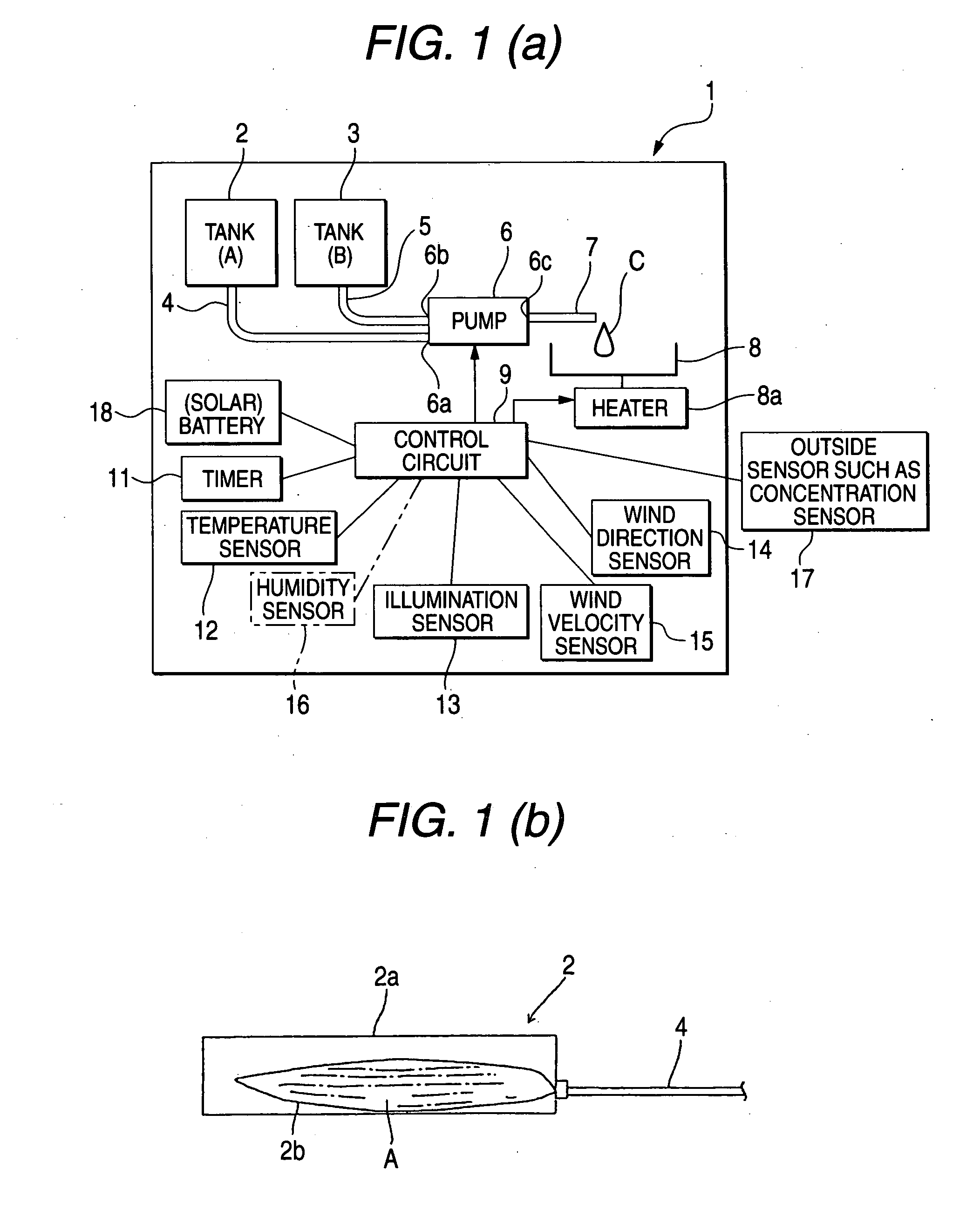
[0074]FIG. 1(a) is a schematic view showing a structure of a chemical diffusion apparatus suitable for diffusing a chemical such as a communication disturbance agent and an attractant in a greenhouse or the like. A chemical diffusion apparatus 1 comprises a first tank 2 filled up with a volatile chemical A and a second tank 3 filled up with a volatile chemical B. The tanks 2 and 3 are filled with the chemicals A and B in a solid or liquid state. The chemicals A and B are supplied from the tanks 2 and 3 to suction holes 6a and 6b of a discharge volume variable type pump 6 via chemical supply paths 4 and 5. Each chemical sucked to the pump 6 is mixed in the pump 6, and then, discharged from a discharge tube 7 connected to a discharge hole 6c of the pump 6. A mixed chemical C is discharged from the discharge tube 7 onto an evaporating dish 8 used as a diffusing means. The mixed chemical C discharged onto the evaporating dish 8 is naturally diffused. A heater 8a may be mounted to the ev...

embodiment 2

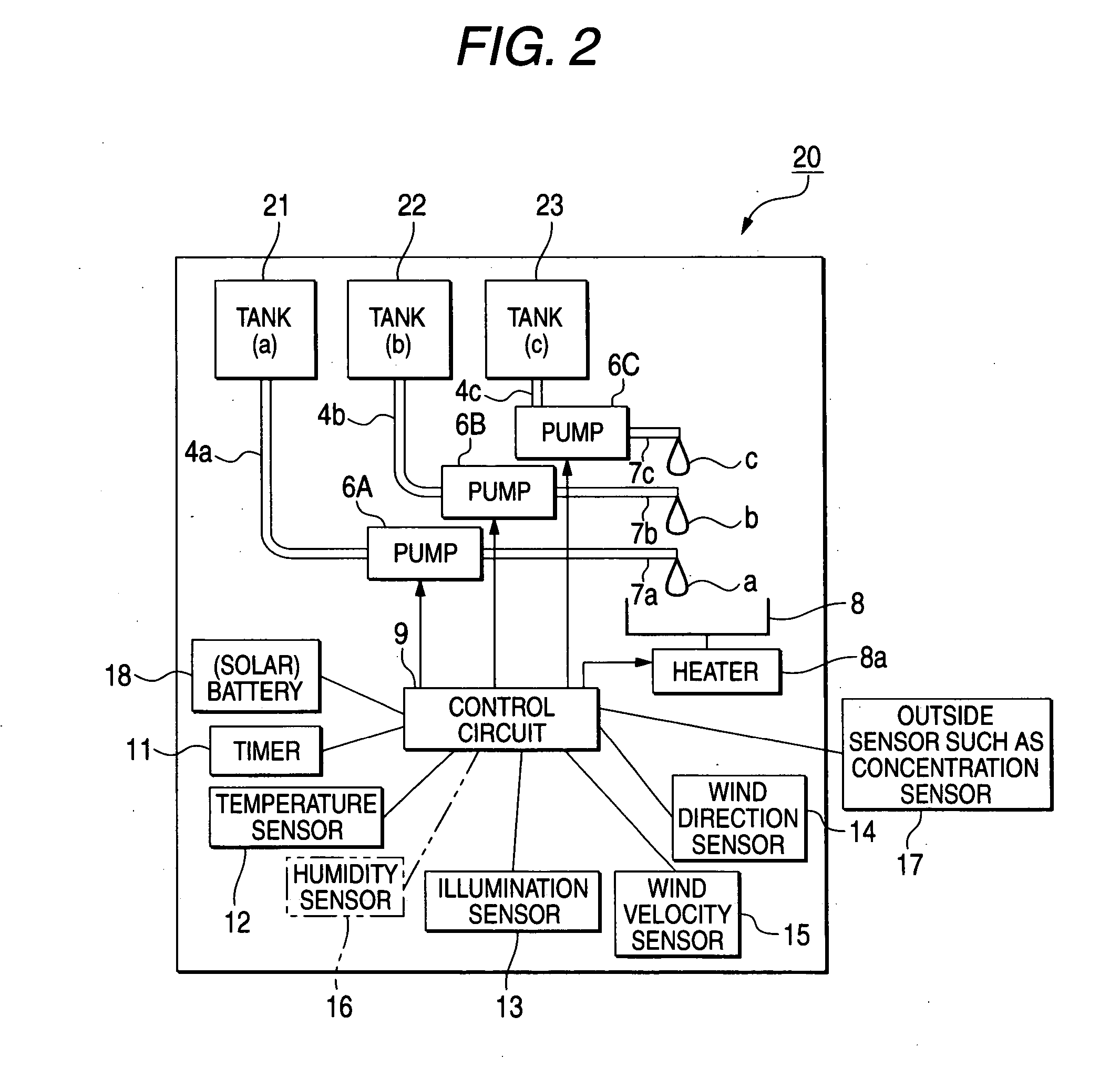
[0082]FIG. 2 is a schematic view showing a structure of a chemical diffusion apparatus in accordance with Embodiment 2. A chemical diffusion apparatus 20 comprises a first tank 21, a second tank 22 and a third tank 23, which are used as a chemical tank and which are respectively filled up with chemicals a, b and c different in constituent. Three pumps 6A to 6C are provided for sucking the respective chemicals a to c through chemical supply paths 4a to 4c, respectively, and discharging the same from discharge tube 7a to 7c. The chemicals a to c are discharged onto a common evaporating dish 8 from the respective discharge tubes 7a to 7c. The control circuit 9 is arranged to be able to control drive of the respective pumps 6A to 6C independently. A structure other than the above is omitted from description since it is similar to that of the chemical diffusion apparatus 1 shown in FIG. 1.

[0083] In the chemical diffusion apparatus 20 having the above structure, the respective tanks 21 t...

embodiment 3

[0089]FIG. 4(a) is a schematic view showing a structure of a chemical diffusion apparatus in accordance with Embodiment 3. A basic structure of a chemical diffusion apparatus 30 in Embodiment 3 is similar to that of the chemical diffusion apparatus 1 shown in FIG. 1. Accordingly, same reference numerals and signs are given to the corresponding parts and description of the parts is omitted.

[0090] The chemical diffusion apparatus 30 comprises a belt conveyor type diffusing means instead of an evaporating dish. That is to say, the chemical diffusion apparatus 30 comprises a belt conveyor 32 over which an endless belt 31 having a surface material capable of absorbing and carrying chemicals such as felt or sponge, for example, are provided and a driving mechanism 33 for driving the belt conveyor 32. The mixed chemical C is discharged from the discharge tube 7 onto the endless belt 31. When the belt conveyor 32 is driven, the endless belt 31 carrying the mixed chemical C is moved along a...


PUM


Abstract

A chemical diffusion apparatus (1) comprises a first tank (2) filled up with a volatile chemical A such as a communication disturbance agent and a second tank (3) filled up with a volatile chemical B. The chemicals A and B are sucked by means of a discharge volume variable pump (6) to be discharged onto an evaporating dish (8) through a discharge tube (7). A mixed chemical C discharged onto the evaporating dish 8 is naturally diffused in the air. A control circuit (9) controls drive of the pump (6). An input side of the control circuit (9) is connected to a timer (11) and an environment parameter detecting means such as a temperature sensor (12), an illumination sensor (13), a wind direction sensor (14) and a wind velocity sensor (15). The control circuit (9) controls discharge and discharge volume of the mixed chemical C from the pump (6) on the basis of detecting results from the respective sensors in accordance with a control program.

Description

TECHNICAL FIELD [0001] The invention relates to a chemical diffusion system, a chemical diffusion apparatus, a chemical diffusion unit and a chemical cartridge, which are used for diffusing chemicals such as a communication disturbance agent and an attractant for a noxious insect, the chemicals including an insect sex pheromone. RELATED ART [0002] There has been a noxious insects extermination method known such that an attractant such as an insect sex pheromone is diffused in the air to cause a communication disturbance of insects for reducing the ovipositional number, and thereby, reducing growth of noxious insects in a farm or the like instead of using an insecticide. For example, known is a method in which a large number of insect sex pheromone dispensers are installed within a predetermined space in cultivation field facilities to naturally diffuse an insect sex pheromone. In such a method, a sex pheromone is put in a plastic tube, which is hooked on a branch of a plant under cu...

Claims


Application Information

Patent Timeline
IPC IPC(8): A62C13/62A01M1/20A01M7/00A01M1/02A61L9/14
CPCA01M1/02A01M1/2038A61L9/14A01M1/205A01M1/2077A01M1/2044
Inventor ITO, KIYOSHIYAMADA, MANABU
Owner SEIKO EPSON CORP
Why Eureka
Try Eureka