Imaging system, imaging controller, and method and program for vertical synchronization

a technology which is applied in the field of imaging controller and vertical synchronization method and program, can solve the problems of limited transmission line length, delay in synchronization of imaging devices, and limited capacity to make use of external synchronization functions

Inactive Publication Date: 2006-11-23
SONY CORP
View PDF2 Cites 18 Cited by
  • Summary
  • Abstract
  • Description
  • Claims
  • Application Information

AI Technical Summary

Benefits of technology

[0026] As described above, according to an embodiment of the present invention, even if the distance between the imaging controller and the imaging device is varied, the imaging controller achieves the external synchronization with an external vertical synchronizing signal automatically, without manual phase adjustment. Thus, no phase delay occurs and the transmission line between the imaging controller and the imaging device can be extended without limitation.

Problems solved by technology

In the case of the invention of patent literature 1, however, if an imaging device is located at a relatively long distance from an imaging controller for relaying an external synchronizing signal to the imaging device, the imaging device is delayed in synchronization by the signal-transmission delay time of the transmission line between the controller and the device.
Thus, the length of transmission lines capable of making use of such function for external synchronization is limited.

Method used


Image

  • Imaging system, imaging controller, and method and program for vertical synchronization
  • Imaging system, imaging controller, and method and program for vertical synchronization
  • Imaging system, imaging controller, and method and program for vertical synchronization

Examples


first embodiment

Imaging System

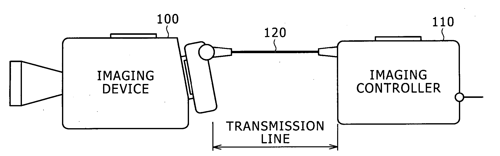
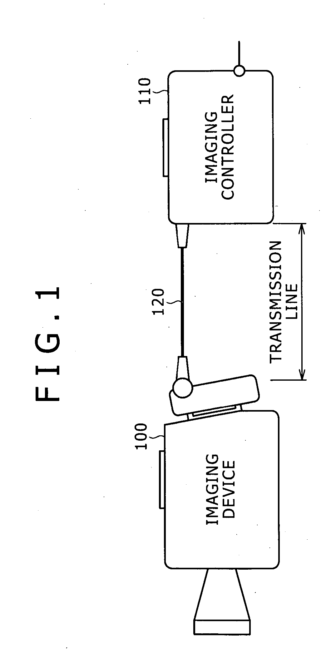
[0038]FIG. 1 is a schematic block diagram of an imaging system according to a first embodiment of the present invention. The imaging system includes an imaging device 100, an imaging controller 110, and a transmission cable 120 connecting the device and the controller.

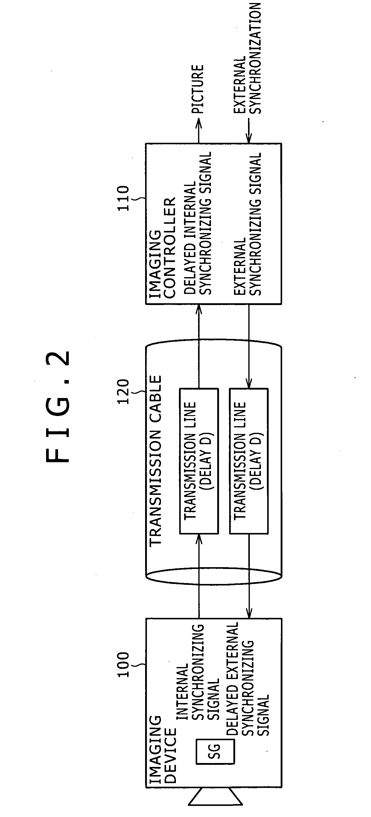
[0039] If the imaging device 100 is alone in producing images of objects, an internal synchronizing signal produced by the imaging device 100 is referred to. The internal synchronizing signal includes an internal horizontal synchronizing signal for the synchronization of horizontal signals of pictures and an internal vertical synchronizing signal for the synchronization of vertical signals of pictures.

[0040] If the imaging device 100 produces images of objects in synchronization with an external installation such as a TV station, the imaging device 100 has to transmit picture signals in accordance with an external synchronizing signal used by the external installation. Namely, the internal synchronizin...

second embodiment

Vertical Synchronizing Signal

[0048] In the external synchronization mode of a conventional imaging device 100, an external vertical synchronizing signal from an imaging controller 110 resets the vertical synchronizing signal-producing circuit in the imaging device 100 to synchronize an internal vertical synchronizing signal with the external vertical synchronizing signal. However, if the transmission cable 120 such as an optical fiber cable between the imaging device 100 and the imaging controller 110 is laid over a long distance, external synchronization cannot be achieved at the imaging controller 110. This problem can be solved as follows.

[0049] The above problem is solved in two steps. The first step is to provide a circuit to measure the round-trip delay due to the transmission cable 120. The second step is to provide a circuit to advance the phase of a vertical-synchronization reset signal (hereinafter “phase-advanced external vertical synchronizing signal”) separated from a...

third embodiment

Horizontal Synchronizing Signal

[0060] Next, the horizontal synchronizing signal will be described below.

[0061]FIG. 6 is a schematic block diagram of an imaging system according to the third embodiment of the present invention. The object of the imaging system is the external synchronization with an external synchronizing signal for horizontal signals. In the imaging system, the imaging device 100 has a horizontal synchronizing signal-producing circuit 300. The imaging controller 110 has a PLL 310.

[0062] The horizontal synchronizing signal-producing circuit 300 produces an internal horizontal synchronizing signal to be used by the imaging device 100 to produce images of objects.

[0063] The PLL 310 includes a phase comparator 312, a loop filter 314, and a VCO (Voltage Controlled Oscillator) 316. The PLL 310 detects the phase difference between an external horizontal synchronizing signal and the internal horizontal synchronizing signal transmitted from the imaging device 100 through...


PUM


Abstract

Disclosed is an imaging system having an imaging device for producing images of objects and picture signals and an imaging controller connected to the imaging device through a transmission line. The imaging device includes a vertical synchronizing signal-producing circuit to produce an internal vertical synchronizing signal for the production of images of objects. The imaging controller includes a delay-measuring circuit and a vertical-synchronization phase-advancing circuit. In the system: the imaging controller transmits a test signal to the imaging device and receives the test signal returned from the imaging device and the delay-measuring circuit measures a delay of a phase of the returned test signal relative to a phase of the original test signal; the vertical-synchronization phase-advancing circuit advances a phase of an external vertical synchronizing signal by the delay and transmits the external vertical synchronizing signal to the imaging device; and the vertical synchronizing signal-producing circuit is reset by a signal transmitted from the vertical-synchronization phase-advancing circuit.

Description

CROSS REFERENCES TO RELATED APPLICATIONS [0001] The present invention contains subject matter related to Japanese Patent Application NO. 2005-150064 filed in the Japanese Patent Office on May 23, 2005, the entire contents of which being incorporated herein by reference. BACKGROUND OF THE INVENTION [0002] 1. Field of the Invention [0003] The present invention relates to an imaging system capable of synchronizing itself with an external vertical synchronizing signal, an imaging controller for synchronization with the external vertical synchronizing signal, and a method and a program for the vertical synchronization. [0004] 2. Description of the Related Art [0005] An imaging device, which produces images of objects and picture signals, produces such images in accordance with an internal synchronizing signal produced by itself. When the imaging device is supposed to synchronize itself with an external device or a TV station, it has to synchronize its internal synchronizing signal with a...

Claims


Application Information

Patent Timeline
Patent Type & Authority Applications(United States)
IPC IPC(8): G01T1/24
CPCH04N5/0733H04N23/00
Inventor NAKAJIMA, TAKATSUGU
Owner SONY CORP
Why Eureka
Try Eureka