Method for minimizing image artifacts and medical imaging system

a technology of image artifacts and medical imaging, applied in tomography, instruments, applications, etc., can solve problems such as inability to achieve optimal correction, and achieve the effect of minimizing artifacts

Active Publication Date: 2006-11-23
SIEMENS HEALTHCARE GMBH
View PDF16 Cites 44 Cited by
  • Summary
  • Abstract
  • Description
  • Claims
  • Application Information

AI Technical Summary

Benefits of technology

[0006] The object of the invention is thus to provide a method and an imaging system, by means of which the artifact

Problems solved by technology

However the problem often arises here that the x-ray detector is relatively small, in particular smaller than with conventional computed tomographs, and thus parts of the object are truncated on some of

Method used


Image

  • Method for minimizing image artifacts and medical imaging system
  • Method for minimizing image artifacts and medical imaging system
  • Method for minimizing image artifacts and medical imaging system

Examples


Embodiment Construction

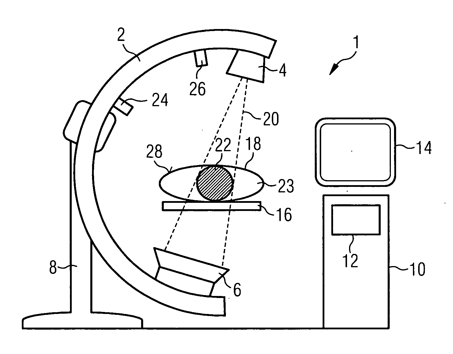
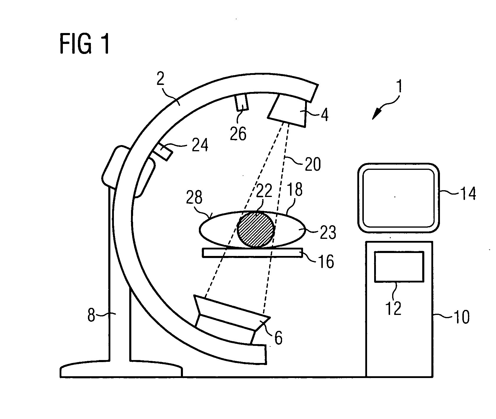
[0024] The invention is described below using the example of an x-ray C-arm system, in which the x-rayed region 22 is smaller than the patient 18. A C-arm system 1 of this type is shown schematically in FIG. 1. The x-ray tube 4 and the x-ray detector 6 are fixed here to opposing ends of a C-arm 2. This C-arm is in turn suspended in a moveable manner on a stand 8 and can thus be moved freely about a patient support 16. The rotation of the C-arm 2 about the support 16 allows a patient 18 lying thereupon to be x-rayed from different projection angles. The beam path of the fan-shaped or tapered x-ray beam is indicated with 20. The drawing clearly shows that the detector 6 is not large enough to record an image of the whole patient 18. Rather a part 23 of the patient does not lie within the x-ray fan.

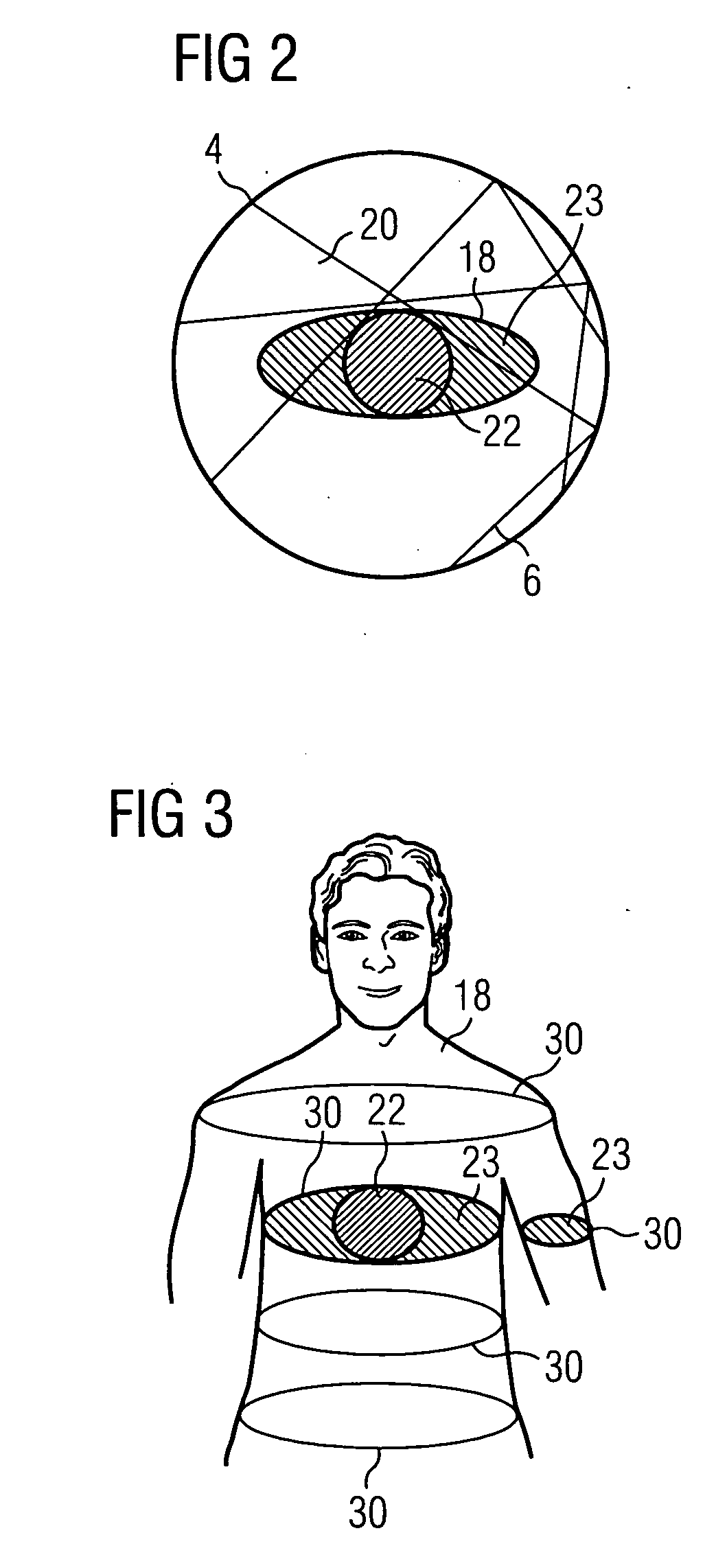
[0025] This problem of the measuring field overshoot is shown even more clearly in FIG. 2. In the centre, the cross-section of the patient 18 is shown schematically as an ellipsoid. Further...


PUM


Abstract

The invention relates to a method for “truncation correction” in an x-ray system, i.e. a correction method during the reconstruction of projection images of an object recorded from different projection angles, if parts of the object do not lie in the field of view of each projection image. The surface of the object is thereby optically detected and used during the reconstruction of projection images to supplement the missing image data.

Description

CROSS REFERENCE TO RELATED APPLICATIONS [0001] This application claims priority of German application No. 10 2005 022 540.3 filed May 17, 2005, which is incorporated by reference herein in its entirety FIELD OF THE INVENTION [0002] The invention relates to a method for minimizing image artifacts during the reconstruction of tomography images of an object from several projection images of the object recorded from different projection angles, as well as a medical imaging system. The said image artifacts are those that are produced as a result of parts of the examined object thereby not lying in the field of view of each projection image (so-called measuring field overshoot). BACKGROUND OF THE INVENTION [0003] With x-ray computed tomography for medical use, a three-dimensional image of the object is calculated by means of a specific method from standard x-ray images, which contain no depth information since they display a projection of a three-dimensional object on a two-dimensional pl...

Claims


Application Information

Patent Timeline
IPC IPC(8): H05G1/60H05G1/02A61B6/00G01N23/00G21K1/12
CPCA61B5/107A61B6/032A61B6/4441G06T2211/432A61B6/5247G06T11/005A61B6/5235Y10S378/901
Inventor BERNHARDT, PHILIPPBOESE, JANPFISTER, MARCUSRAHN, NORBERT
Owner SIEMENS HEALTHCARE GMBH
Why Eureka
Try Eureka