
Organic electroluminescent device

a technology of electroluminescent devices and electroluminescent tubes, which is applied in the direction of luminescnet screens, discharge tubes, natural mineral layered products, etc., can solve the problems of undeveloped devices with high efficiency and high durability

Active Publication Date: 2006-11-23
UDC IRELAND +1
View PDF2 Cites 892 Cited by
  • Summary
  • Abstract
  • Description
  • Claims
  • Application Information

AI Technical Summary

Benefits of technology

[0006] Other and further features and advantages of the inve

Problems solved by technology

However, devices having both high efficiency and high durability have not been developed.

Method used


Image

  • Organic electroluminescent device
  • Organic electroluminescent device
  • Organic electroluminescent device

Examples


examples

[0105] The compound represented by formula (I) or (II) in the present invention can be synthesized according to a known synthesis method using, as a starting material, the compound (A) that can be synthesized, for example, by methods described in Journal of Organic Chemistry 53, 786, (1988), G. R. Newkome et al., on page 789, left column, line 53 to right column, line 7, page 790, left column, lines 18 to 38, and page 790, right column, lines 19 to 30, or a combination of these methods.

1. Making of the Organic Electroluminescent Devices

(1) Making of the Organic Electroluminescent Device of the Present Invention

[0106] A glass substrate, having an ITO film of thickness 0.5 mm and a square size of 2.5 cm on each side (surface resistance 10Ω□, manufactured by GEOMATEC CO., LTD.), was placed in a cleaning vessel and ultrasonically cleaned in a solution of 2-propanol, followed by UV-ozone treatment for 30 minutes. On this transparent anode (ITO film), the following organic compound ...


PUM

PropertyMeasurementUnit
Percent by massaaaaaaaaaa
Thicknessaaaaaaaaaa

Abstract

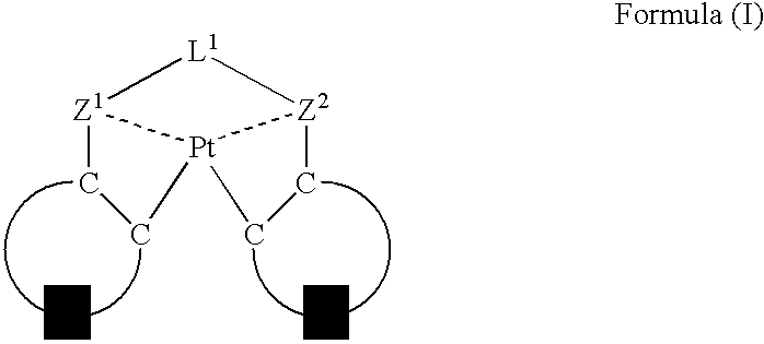
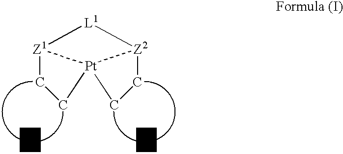
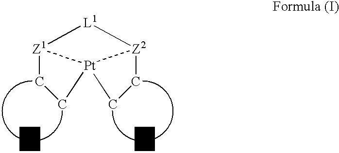
An organic electroluminescent device having a pair of electrodes and at least one organic layer interposed between the pair of electrodes, in which the at least one organic layer contains at least one compound represented by formula (I): wherein, Z1 and Z2 each independently represent a nitrogen-containing aromatic six-membered ring coordinated to the platinum through a nitrogen atom; Q1 represents a group of atoms necessary for forming, together with the —C—C—, a nitrogen-containing aromatic five-membered ring; L1 represents a single bond or a divalent linking group; and n is 0 or 1.

Description

FIELD OF THE INVENTION [0001] The present invention relates to an organic electroluminescent device (hereinafter, referred to also as “organic EL device,”“light-emitting device,” or “device”) capable of emitting light by converting electric energy to light. BACKGROUND OF THE INVENTION [0002] Energetic studies and developments are being made as to organic electroluminescent devices, because highly luminescent emission is obtained from these devices with low-voltage driving. The organic electroluminescent devices are constituted of an organic layer and a pair of electrodes between which the organic layer is sandwiched. In such devices, electrons injected from the cathode are recombined with holes injected from the anode in the organic layer, to produce excitons, whose energy is utilized to emit light. [0003] Improvement in the efficiency of devices has been recently made by using a phosphorescence-emitting material. Iridium complexes, platinum complexes, and the like are such a phosph...

Claims


Application Information

Patent Timeline
IPC IPC(8): B32B19/00
CPCC09K11/06C09K2211/1029C09K2211/1044C09K2211/1059C09K2211/1092H01L51/5016H01L51/0058H01L51/0072H01L51/0081H01L51/0085H01L51/0087C09K2211/185Y10S428/917H10K85/626H10K85/324H10K85/346H10K85/342H10K85/6572H10K50/11H10K2101/10
Inventor ISE, TOSHIHIRO
Owner UDC IRELAND
Learn More