Method for tomographically displaying a cavity by optical coherence tomography (OCT) and an OCT device for carrying out the method

a tomographic and cavity technology, applied in the field of tomographically displaying cavities, can solve the problems of inability to utilize oct for examination, inability to recalibrate manually, and limited use of o

Active Publication Date: 2006-11-23
SIEMENS HEALTHCARE GMBH
View PDF6 Cites 113 Cited by
  • Summary
  • Abstract
  • Description
  • Claims
  • Application Information

AI Technical Summary

Benefits of technology

[0013] The inventors recognized that it is automatically possible to directly influence both the change in the length of the optical fiber in a moved catheter as well as indirectly correct the effect of such changes in length in the generated image if, with the aid of image analysis, an object which is known in its dimension is continuously registered in the scanning region of the OCT catheter and the displayed dimension thereof is compared with the known actual dimension and is re-corrected according to a detected change in dimension. The correction measure can for example be a purely electronically executed change in the scale of the display of a scanned image, or one of the light paths of the measuring or reference beam can also be directly corrected in terms of its length. The delay time of the light through the measuring or reference path may also be influenced, and this also corresponds to a change in the length of the light path. A combination of a plurality of variants is also possible, in particular if the developments of the individual variants have different reaction times and adjustment speeds. Thus it may for example be advantageous to firstly electronically compensate, in the image itself, a change in the scale of the image display as soon as this is detected and to subsequently make a change in the mechanical length of a light path.
[0014] According to this basic idea the inventors propose improving the method, known per se, for tomographically displaying a cavity, preferably a blood vessel, by Optical Coherence Tomography (OCT), wherein, as is known, a scanning head with a catheter is introduced into the cavity to be optically scanned and the surroundings of the scanning head are shown in a tomographical display on the basis of detected interferences and their intensities between a measuring light beam and a reference light beam, wherein the path length of the measuring light beam in the catheter can change as a result of a movement of the catheter and brings about a change in the display scale. The improvement lies in the fact that a possible change in the path length of the measuring light beam in the event of a movement of the catheter is electronically determined and automatically compensated.

Problems solved by technology

The use of OCT is limited by the penetration depth of electromagnetic radiation into the object being examined and by the bandwidth.
The changed length of the OCT catheter, or its core, changes the calibration, so length measurements in photographs which are caused by a movement of the catheter contain substantial errors and thus cannot be utilized for the examination.
Manual recalibration is not possible as the catheter moves very quickly.

Method used


Image

  • Method for tomographically displaying a cavity by optical coherence tomography (OCT) and an OCT device for carrying out the method
  • Method for tomographically displaying a cavity by optical coherence tomography (OCT) and an OCT device for carrying out the method
  • Method for tomographically displaying a cavity by optical coherence tomography (OCT) and an OCT device for carrying out the method

Examples


Embodiment Construction

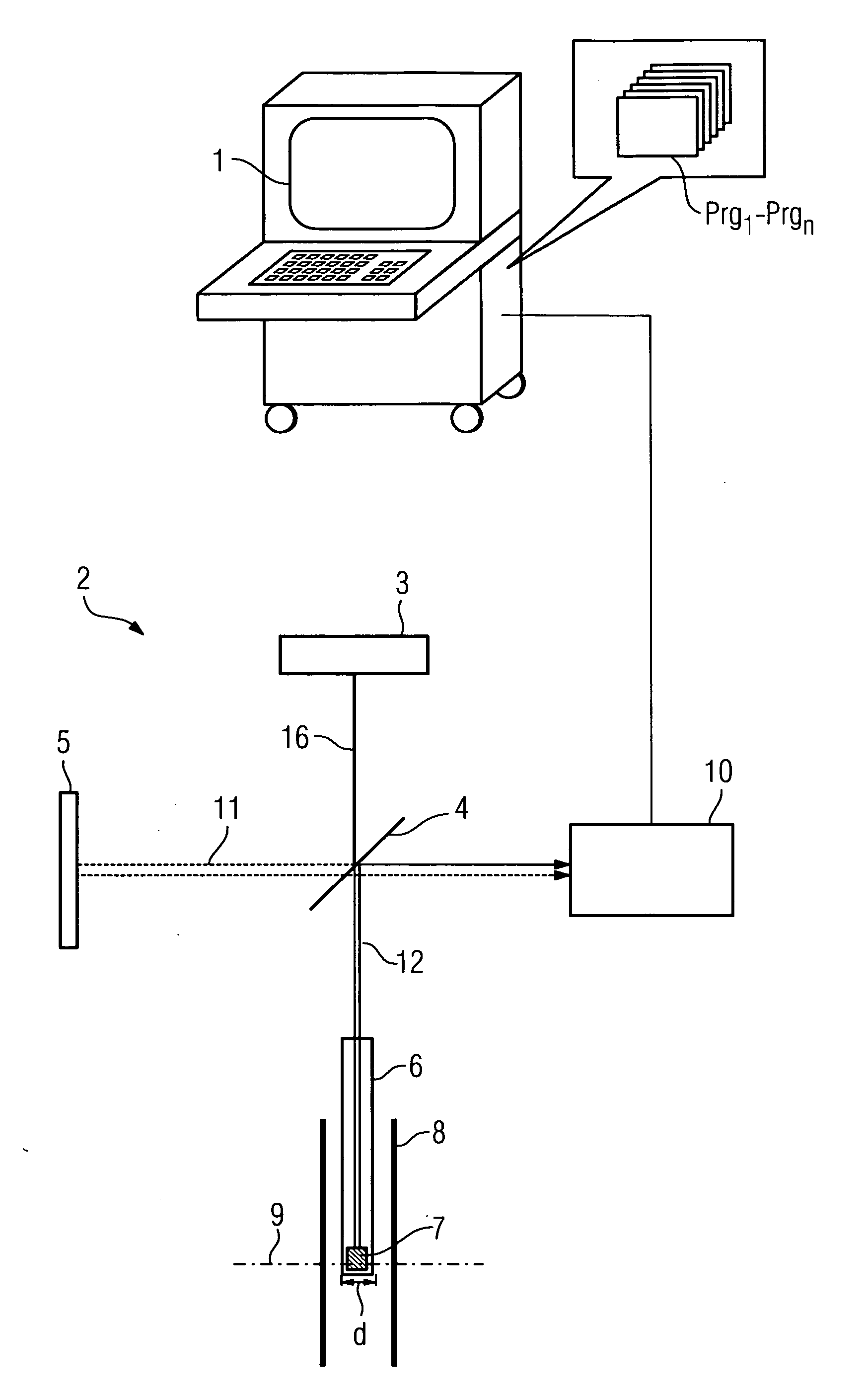
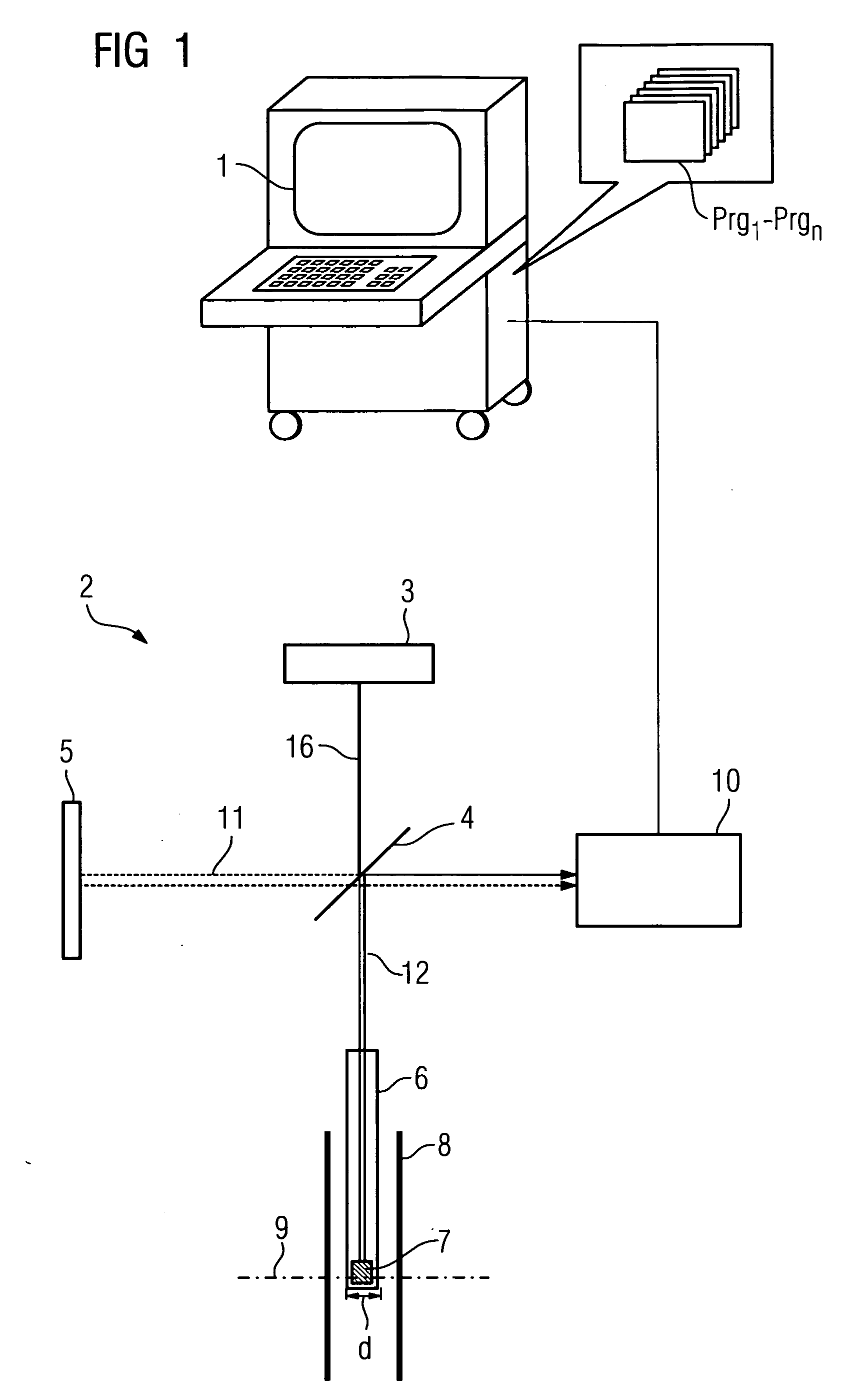
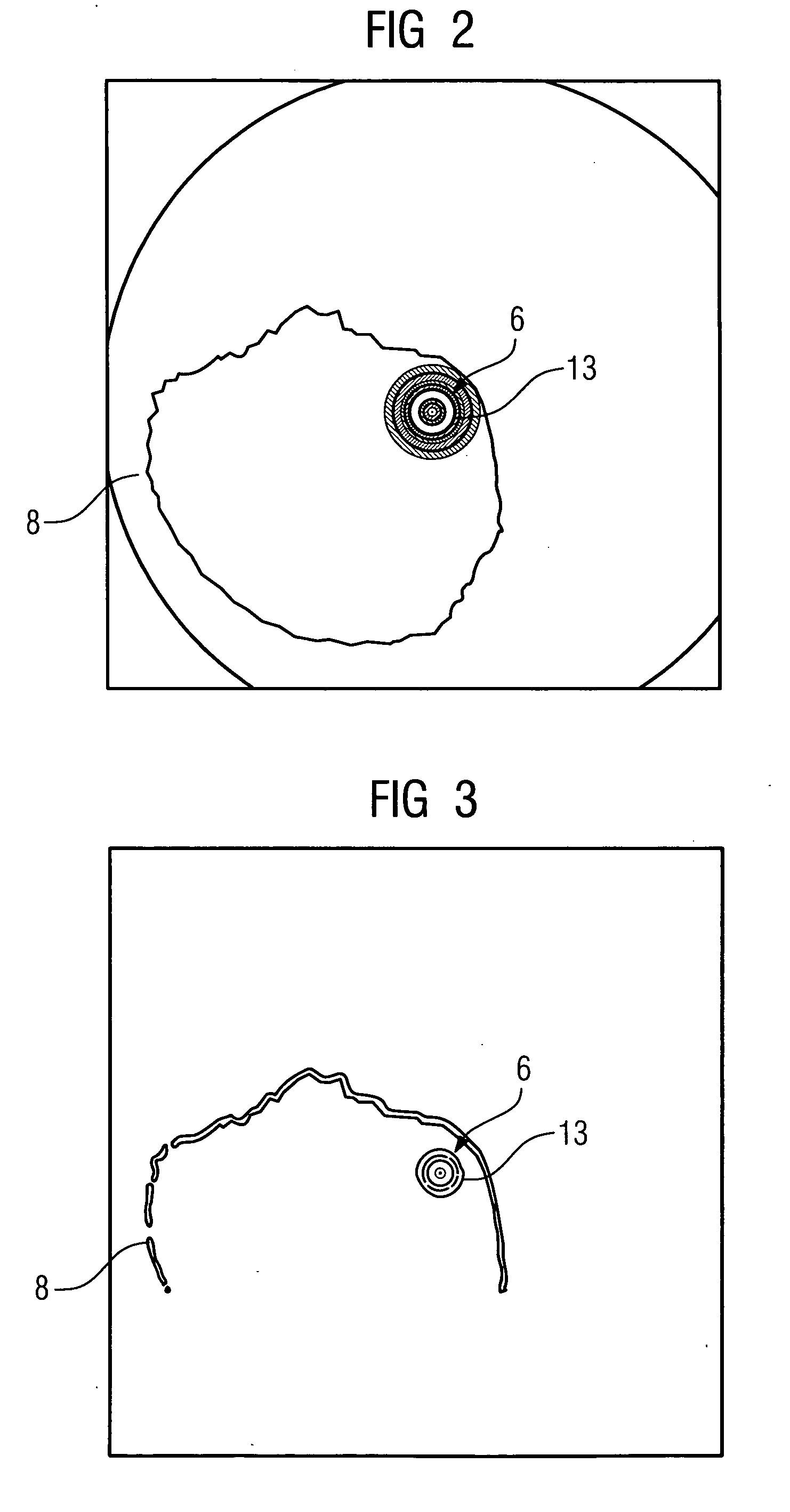
[0039]FIG. 1 shows an OCT device known per se with a computing unit 1 and the actual OCT unit 2. This is constructed from a laser 3 which, via a common light path 16, emits coherent light radiation to a semi-transparent mirror 4. At this semi-transparent mirror 4 a portion of the light is guided on the measuring path 12 to the scanning head 7 of the catheter 6 where the surroundings of the blood vessel 8 (schematically shown here) are scanned in a plane 9. The reflected light is then returned to the measuring path 12 and reflected at the semi-transparent mirror to the subsequent detector 10. At the same time, a decoupled portion of the light is conveyed to the reference path 11 at the semi-transparent mirror 4. A mirror 5, which conveys the light back and through the semi-transparent mirror 4 to the detector 10, is located in this reference path 11.

[0040] The two overlapping light beams are detected in the detector in the region of the scanning head 7 with respect to their interfer...


PUM


Abstract

The invention relates to a method for tomographically displaying a cavity by optical coherence tomography (OCT) and to an OCT device, wherein the path length of a measuring light beam in the catheter can change as a result of a movement of the catheter and brings about a change in the display scale, wherein a possible change in the path length of the measuring light beam in the event of a movement of the catheter is electronically determined and automatically compensated.

Description

CROSS REFERENCE TO RELATED APPLICATIONS [0001] This application claims priority of German application No. 102005021061.9 filed May 6, 2005, which is incorporated by reference herein in its entirety. FIELD OF THE INVENTION [0002] The invention relates to a method for tomographically displaying a cavity, preferably a blood vessel, by Optical Coherence Tomography (OCT), in that a scanning head with a catheter is inserted into the cavity to be optically scanned and the surroundings of the scanning head are displayed in a tomographical display on the basis of detected interferences and their intensities between a measuring light beam and reference light beam, wherein the path length of the measuring light beam in the catheter can change as a result of a movement of the catheter and brings about a change in the display scale. [0003] The invention also relates to an OCT (=Optical Coherence Tomography) device for tomographically displaying an examined object, comprising a coherent laser lig...

Claims


Application Information

Patent Timeline
Patent Type & Authority Applications(United States)
IPC IPC(8): A61B5/05
CPCA61B5/0066A61B5/6852A61B5/02007
Inventor KLEEN, MARTINPFISTER, MARCUSREDEL, THOMAS
Owner SIEMENS HEALTHCARE GMBH
Why Eureka
Try Eureka