Magnetic sheet for radio frequency identification antenna, method of manufacturing the same, and radio frequency identification antenna using the same

a radio frequency identification and antenna technology, applied in the direction of antennas, magnetic bodies, magnetic materials, etc., can solve the problems of high inferiority ratio, difficult to tune the lc resonance circuit, increased data communication distance,

Inactive Publication Date: 2006-11-30
AMOTECH
View PDF5 Cites 74 Cited by
  • Summary
  • Abstract
  • Description
  • Claims
  • Application Information

AI Technical Summary

Benefits of technology

[0018] The inventors have proved the fact that these inventors could manufacture a magnetic sheet having the thin and uniform thickness of 0.35 mm or less in comparison with an existing metal sheet at the low cost with the minimum p

Problems solved by technology

Accordingly, if a magnetic material having a higher magnetic permeability is employed as a material of the absorber sheet for the tag antenna, a data communication distance is increased and an error probability of data can be lowered.
In the conventional technology, it is very difficult to tune the LC resonance circuit since an inductance deviation of the transponder antenna is serious due to the non-uniformity of the thickness of these ferrites.
Moreover, the non-uniformity exceeding the error range of the thickness may cause difficulty of an installation when a magnetic sheet is attached in a battery pack space, and an error occurs in the process of the formation and transmission of binary code data during the mutual transmission process of data, to thereby make a very high inferiority ratio, as well.
Accordingly, an amount of the power consumption increases.
In this case, the commun

Method used

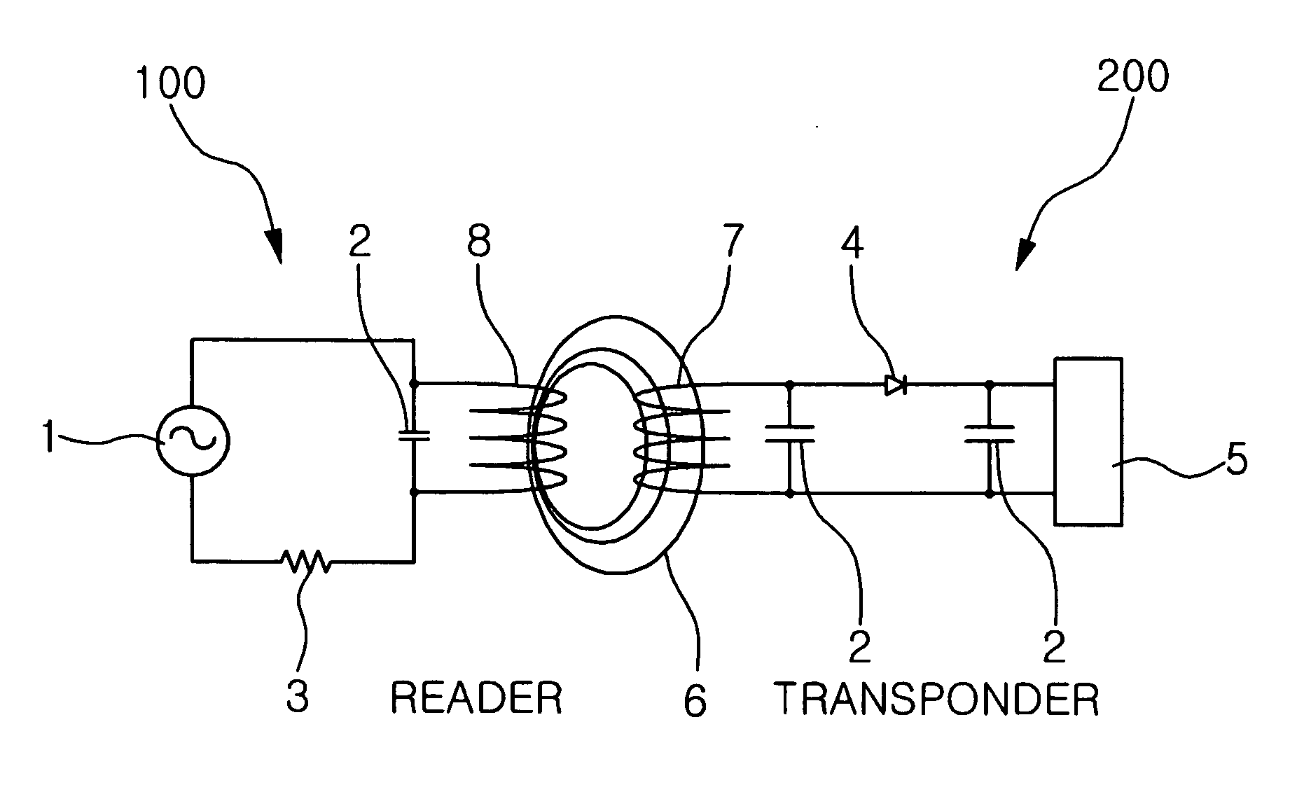
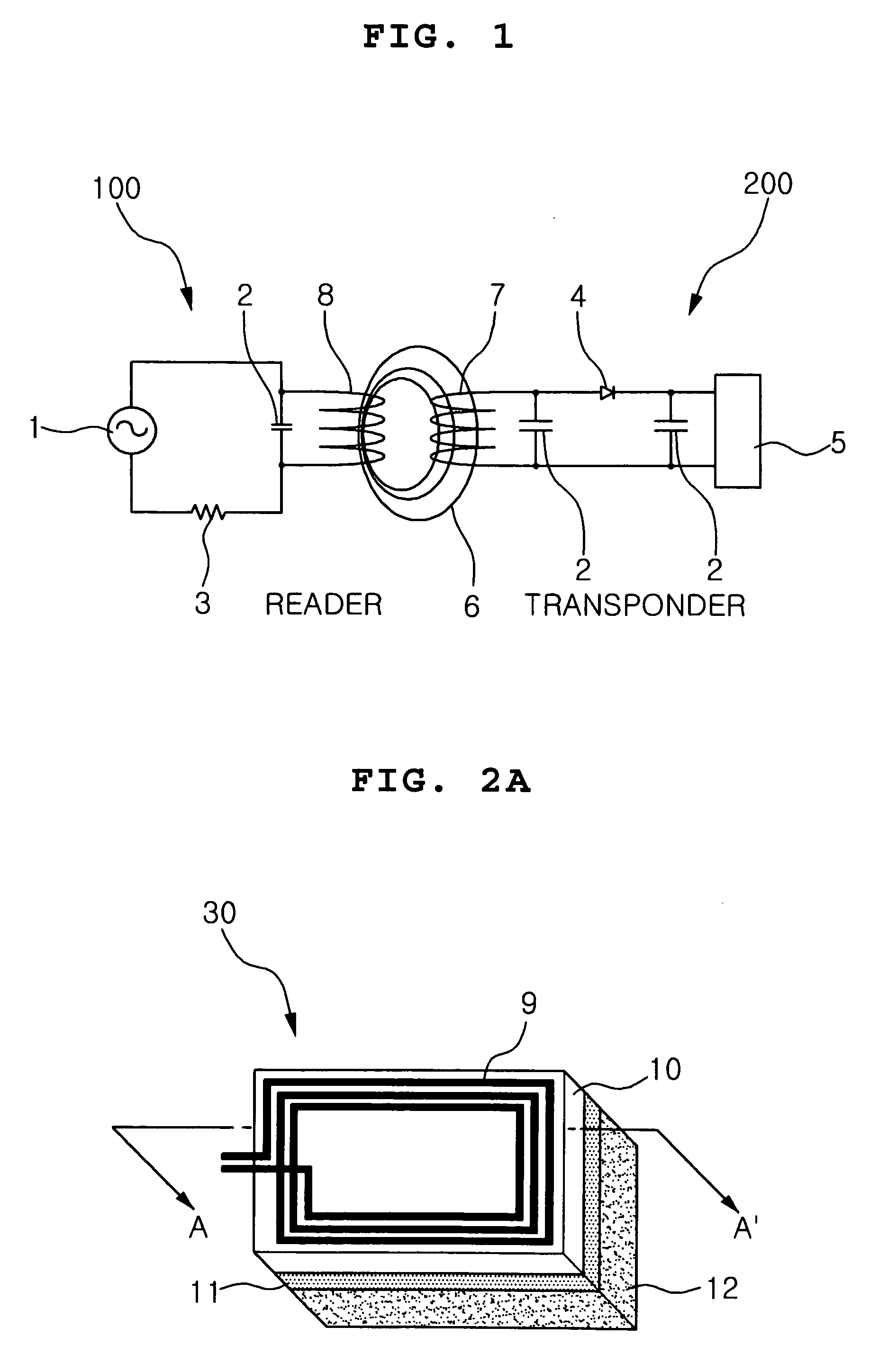
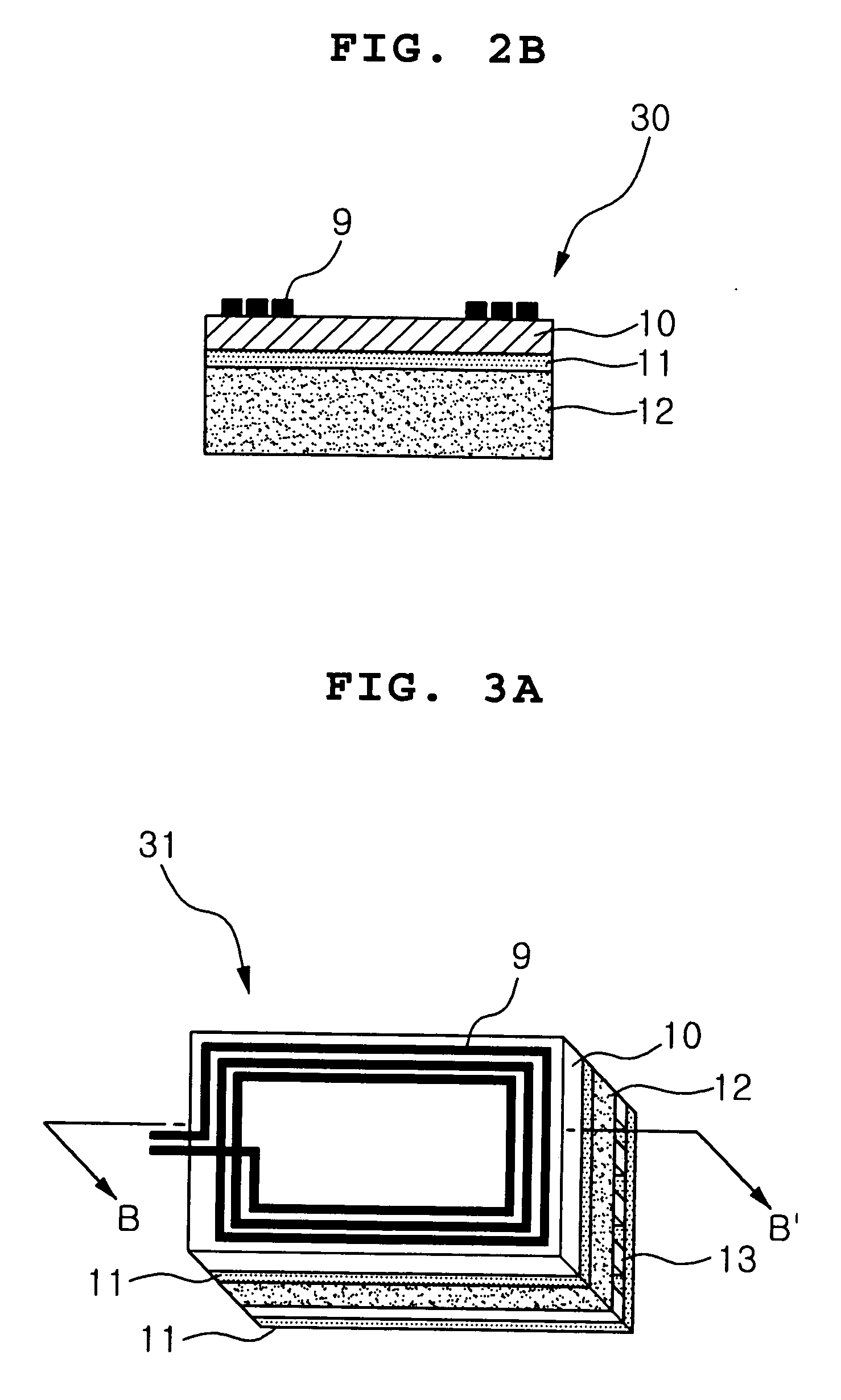

Image

  • Magnetic sheet for radio frequency identification antenna, method of manufacturing the same, and radio frequency identification antenna using the same
  • Magnetic sheet for radio frequency identification antenna, method of manufacturing the same, and radio frequency identification antenna using the same
  • Magnetic sheet for radio frequency identification antenna, method of manufacturing the same, and radio frequency identification antenna using the same

Examples


third and fourth embodiments

[0124] As an alloy for a magnetic sheet according to third and fourth embodiments, an amorphous alloy of a composition of Fe73.5Cu1Nb3Si13.5B9 being FINEMET (registered trademark) of the Japanese Hitach corporation or Vvitroperm (registered trademark) of the German Vacuumschmelze corporation was used. Except that the magnetic sheet was made of 0.20 mm thick (third embodiment) or 0.25 mm thick (fourth embodiment), the RFID antenna was manufactured in the same method as that of the first embodiment.

fifth embodiment

[0125] Fe—B was used as a starting material in manufacturing an alloy for a magnetic sheet. In order to fit for a composition ratio, electrolytic iron (Fe) and Zr were added to manufacture an amorphous alloy of a composition of Fe90Zr7B3 Except that the magnetic sheet was made of 0.25 mm thick, the RFID antenna was manufactured in the same method as that of the first embodiment.

sixth embodiment

[0126] Co—B was used as a starting material in manufacturing an alloy for a magnetic sheet. In order to fit for a composition ratio, elements of Co, Si, Fe, Ni and Cr were added to manufacture an amorphous alloy of a composition of Co76(Si, B)15Fe4 (Cr, Ni)5. Except that the magnetic sheet was made of 0.40 mm thick, the RFID antenna was manufactured in the same method as that of the first embodiment.


PUM


Abstract

Provided are a magnetic sheet for use in a radio frequency identification (RFID) antenna, an RFID antenna including the magnetic sheet, and a method of manufacturing the magnetic sheet, in which the magnetic sheet includes an amorphous alloy selected from the group consisting of Fe—Si—B, Fe—Si—B—Cu—Nb, Fe—Zr—B and Co—Fe—Si—B. The magnetic sheet is made by laminating amorphous alloy ribbons made of an amorphous alloy between magnetic sheet layers formed of alloy powder including at least one amorphous alloy and then compression-molding the amorphous alloy ribbons, to thereby control microcrack of the amorphous alloy ribbons and enhance characteristic of an end-product. The magnetic sheet is also thin, and has an excellent magnetic permeability, and a simple manufacturing process.

Description

BACKGROUND OF THE INVENTION [0001] 1. Field of the Invention [0002] The present invention relates to a magnetic sheet for use in a radio frequency identification (RFID) antenna, a method of manufacturing the same, and a radio frequency identification (RFID) antenna using the magnetic sheet. More particularly, the present invention relates to a magnetic sheet for use in a radio frequency identification (RFID) antenna, a method of manufacturing the same, and a radio frequency identification (RFID) antenna using the magnetic sheet, in which the magnetic sheet is a mono-layer structure which is made of alloy powder including at least one amorphous alloy, or a multilayer structure which is formed by laminating an amorphous alloy ribbon made of an amorphous alloy between magnetic sheet layers and compression-molding the same. [0003] 2. Description of the Related Art [0004] Recently, a radio frequency identification (RFID) system communicating data between a transponder including an integr...

Claims


Application Information

Patent Timeline
IPC IPC(8): H01F1/153
CPCG06K19/07771H01Q17/00H01Q1/22
Inventor YANG, JAE SUKLIM, HYEON CHULLEE, BYOUNG KILEE, YONG SUPKIM, YONG HYUNSONG, YONG SULKWON, SANG KYUNKIM, BEOM JIN
Owner AMOTECH
Why Eureka
Try Eureka